Encapsulation of waste

a technology of encapsulation and waste, applied in the field of ceramic materials, can solve the problems of reducing the flexibility of the plant, and reducing the volume of high-level waste produced, so as to reduce the total waste volume, improve the flexibility of the plant, and maintain the effect of precursor feed ra

Inactive Publication Date: 2006-07-18
NUCLEAR DECOMMISSIONING AUTHORITY
View PDF17 Cites 7 Cited by
  • Summary
  • Abstract
  • Description
  • Claims
  • Application Information

AI Technical Summary

Benefits of technology

[0066]Fuel assembly designs vary from reactor to reactor and consequently so will the composition of the waste stream. One option is to have a dedicated precursor formulation and waste loading for each fuel assembly type. That approach should enable minimisation of total waste volumes. However, improved plant flexibility can be achieved if a single precursor formulation and constant precursor feed rate is possible. Advantageously, it has been found that the same precursor formulation can be used at a fixed quantity per tonne of fuel reprocessed for a range of fuel assembly designs. That is, it has been found that a range of waste stream compositions, arising from a selection of fuel assemblies processed by an electrochemical dissolution route, can be immobilised. The phase assemblage contains zirconolite, hollandite, perovskite and, commonly, loveringite. Commonly, metallic phases are also formed. The flexibility is facilitated by variations in the relative amounts of the phases. In the case of a fuel assembly having higher levels of iron and chromium there is also the formation of a spinel phase. Thus for the range of fuel assemblies the precursor composition can be the same and the quantity of precursor per tonne of fuel reprocessed can be constant allowing improved operational stability of the waste immobilisation plant.

Problems solved by technology

However, waste streams which are likely to arise in the future due to developments to the so-called PUREX process (so-called Advanced PUREX process) may not be suitable for containment by the vitrification technique due principally to relatively high levels of iron, chromium and zirconium which result from the non-fuel components of fuel assemblies which are also taken into solution in the envisaged new reprocessing techniques.
The high level waste produced by more modern and improved Advanced PUREX reprocessing routes, however, contains such high quantities of inert material from the fuel assembly that vitrification at the same waste loading would roughly quadruple the volume of high level waste produced per tonne of fuel reprocessed.
However, it is considered that the conventional “Synroc” formulation may have disadvantages for encapsulating the waste envisaged from reprocessed fuel shortly to occur.
In particular, because “Synroc” typically comprises a waste loading of only about 20 weight % and generally less than 30 weight %, the large amount of inert material produced with the new reprocessing methods will result in a large increase in the volume of the final immobilised waste.

Method used


Image

  • Encapsulation of waste
  • Encapsulation of waste

Examples


example 1

[0068]In the encapsulation of a real waste from Advanced PUREX reprocessing, the denitrated waste liquor containing the waste ions to be encapsulated will be blended with the precursor containing the TiO2, CaO and BaO to form the slurry mixture. The slurry will then be dried and calcined as described above.

[0069]For experimental convenience, however, the mixture of waste ions and TiO2, CaO and BaO in this example was prepared by a slightly different route. Provided there has been homogenous mixing, the manner of forming the slurried mixture of waste, TiO2, CaO and BaO is not important, as the calcining step renders the history of the slurry irrelevant.

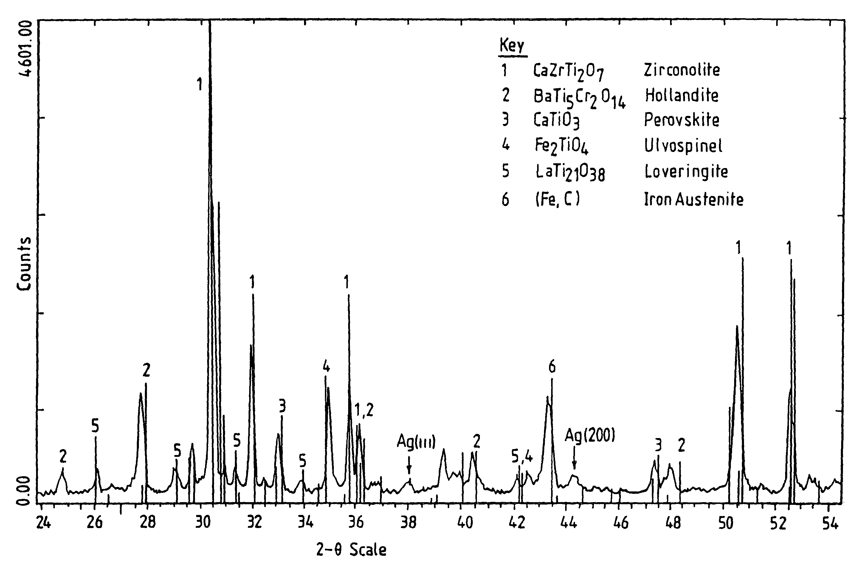
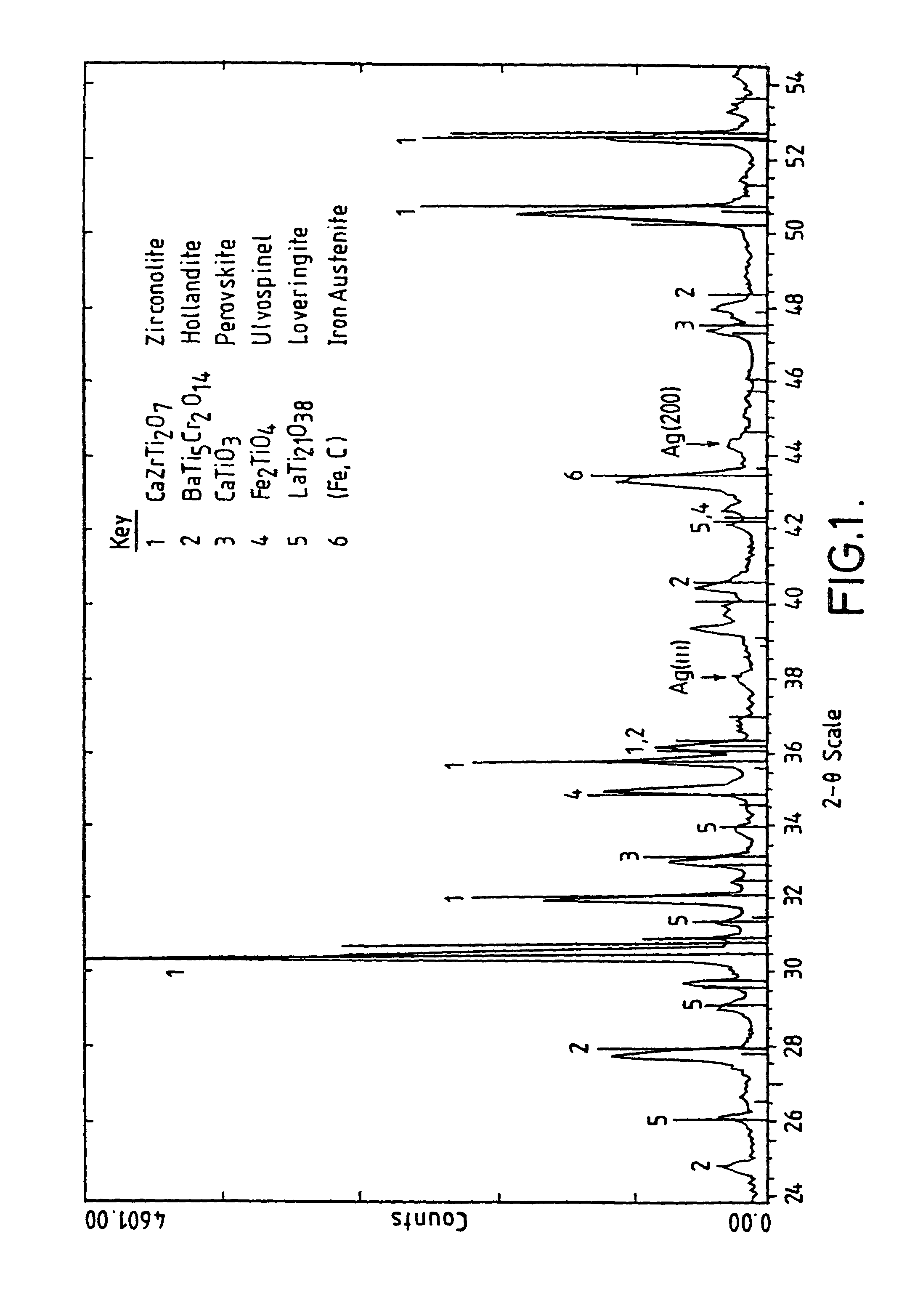
[0070]The composition of the simulated waste used in the experiment is given in Table 2. The relative amounts of the components in weight % are based on the oxides. The list of components in Table 2 does not include all of the components listed in Table 1 because many of the components were replicated by a simulant. Neodymium was used ...

example 2

[0079]The ability to immobilise different waste stream compositions due to different reactor fuel assembly designs was investigated. The fuel assembly compositions and waste stream compositions for various fuel assembly types denoted A–H for both PWR and BWR plants are given in Tables 3 and 4. Table 3 contains the raw data for each fuel assembly type whilst in Table 4 these figures have been converted to the waste oxides in the raffinate per tonne of fuel reprocessed—this conversion has been carried out because the chemical separation stage in a reprocessing plant operates on a throughput based on tonnes of fuel per day. It was investigated whether improved plant flexibility could be achieved by using a single precursor formulation and constant precursor feed rate for all assembly types. Consequently, in this example it was tested whether the same precursor could be used at a fixed quantity per tonne of fuel reprocessed for the range of different fuel assembly and waste compositions...


PUM

PropertyMeasurementUnit
weight %aaaaaaaaaa
weight %aaaaaaaaaa
weight %aaaaaaaaaa

Abstract

A ceramic waste immobilizing material for the encapsulation of high level radioactive waste (HLW), e.g. resulting from the reprocessing of irradiated nuclear fuel. The ceramic waste immobilising material enables waste ions from at least fission products in irradiated nuclear fuel to be dissolved in substantially solid solution form. The ceramic waste immobilising medium has a matrix comprising phases of hollandite, perovskite and zirconolite in which the waste ions are dissolved. The invention also includes a method of immobilizing HLW from reprocessed nuclear fuel assemblies comprising the steps of mixing a liquor containing the HLW with a precursor material comprising oxides or oxide precursors of at least titanium, calcium and barium to form a slurry, drying the slurry, and calcining the dried slurry under a reducing atmosphere to form a powder comprising 30–65 weight % waste.

Description

BACKGROUND OF THE INVENTION[0001]1. Technical Field[0002]The present invention relates to a ceramic material for the encapsulation of high level radioactive waste, e.g. resulting from the reprocessing of irradiated nuclear fuel. The term reprocessing used herein includes not only processing which separates irradiated fuel to provide new fuel products but any processing which includes any separation of irradiated fuel, e.g. any so-called spent fuel reconditioning process.[0003]2. Related Art[0004]Vitrification has been the preferred method of encapsulating highly active wastes comprising fission products resulting from the reprocessing of irradiated fuels. The method involves the incorporation of the waste within a continuous amorphous matrix. However, waste streams which are likely to arise in the future due to developments to the so-called PUREX process (so-called Advanced PUREX process) may not be suitable for containment by the vitrification technique due principally to relativel...

Claims


Application Information

Patent Timeline
Patent Type & Authority Patents(United States)
IPC IPC(8): G21F9/34G21F9/20G21F9/28C04B35/00G21F9/16G21F9/30
CPCG21F9/162G21F9/16
Inventor MADDRELL, EWAN ROBERTCARTER, MELODY LYN
Owner NUCLEAR DECOMMISSIONING AUTHORITY
Why Eureka
Try Eureka