Cathode ray tube

a cathode ray tube and tube body technology, applied in the direction of discharge tube/lamp details, discharge tube main electrodes, discharge tube solid thermionic cathodes, etc., can solve the problems of insufficient power saving, limit in the reduction of power consumption of heaters,

Inactive Publication Date: 2006-07-18
HITACHI DISPLAYS
View PDF6 Cites 2 Cited by
  • Summary
  • Abstract
  • Description
  • Claims
  • Application Information

AI Technical Summary

Benefits of technology

[0018]Accordingly, the present invention has been made to solve the above-mentioned drawbacks of the related art and it is an object of the present invention to provide a cathode ray tube having an electron gun provided with an indirectly heated cathode structure which can reduce the power consumption of a heater by decreasing the temperature elevation of respective electrodes which constitute the indirectly heated cathode structure.

Problems solved by technology

However, when the multiplex coil winding is merely applied to the heater leg portion, the electric resistance reduction effect is still small and hence, there exists a limit with respect to the reduction of power consumption of the heater.
However, there has been known no related art which discloses or takes into an account the constitution which can reduce the power consumption positively thus realizing the low power consumption while enhancing the various electrical characteristics by improving the electrode structure of the indirectly heated cathode structure and the structure of the heated heater.
This demand for the low power consumption constitutes one of contemporary critical issues and the significance thereof is steadily increasing.
Further, with respect to a heating heater of three-electron-gun type which is generally adopted by the cathode ray tube or the like, the heater having the specification in which the rating of the heater is 6.3V–300 mA (one electron gun: 0.63 W per one heater) is popularly used and hence, the sufficient power saving has not been realized.

Method used


Image

  • Cathode ray tube
  • Cathode ray tube
  • Cathode ray tube

Examples


Embodiment Construction

[0029]Preferred embodiments of the present invention are explained in detail in conjunction with drawings showing the embodiments.

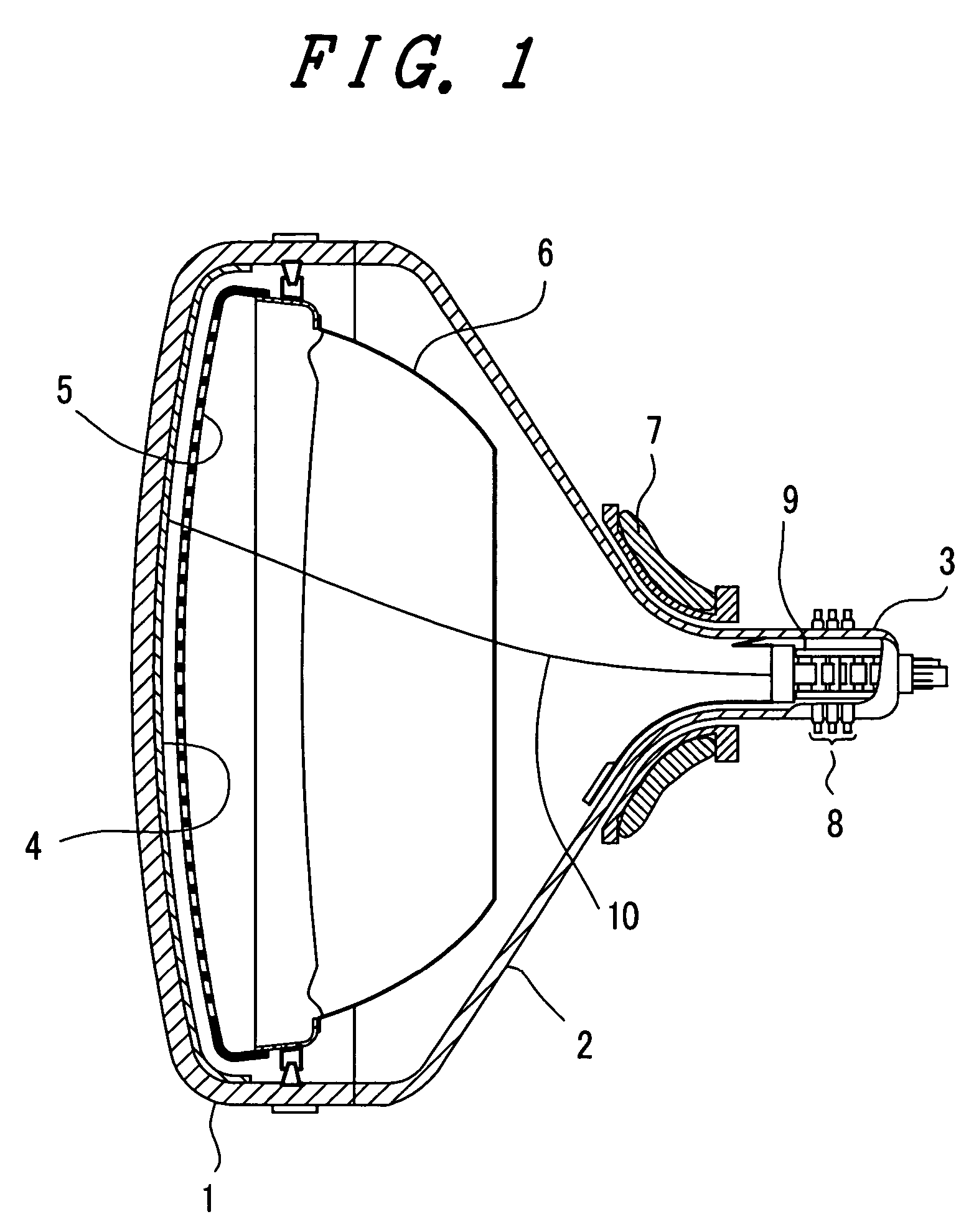
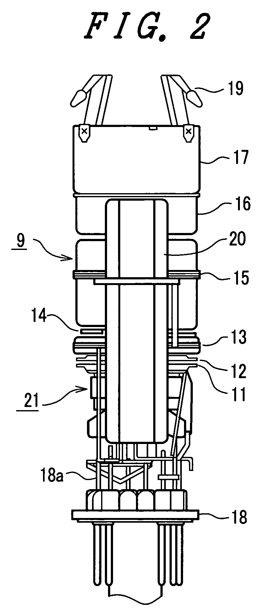
[0030]FIG. 1 is a schematic cross-sectional view showing the schematic constitution of a shadow-mask type color cathode ray tube for explaining one embodiment of a cathode ray tube according to the present invention. In the drawing, numeral 1 indicates a panel portion, numeral 2 indicates a funnel portion, numeral 3 indicates a neck portion, numeral 4 indicates a phosphor screen which is formed by applying a phosphor to an inner surface of the panel portion 1, numeral 5 indicates a shadow mask which constitutes a color selection electrode, numeral 6 indicates a magnetic shield which blocks an outer magnetic field (earth magnetism), numeral 7 indicates a deflection yoke, numeral 8 indicates an outer magnetism correction device, numeral 9 indicates an electron gun provided with an indirectly heated cathode which irradiates three electron beams, and numeral ...


PUM


Abstract

The indirectly heated cathode structure includes a base metal having a thermal electron emitting material layer, a cylindrical sleeve holding the base metal at one end portion thereof and housing a heating heater in the inside thereof, an support having a large-diameter portion and g a small-diameter portion, and a cathode disc having a large-diameter portion at the leg-portion-side of the heating heater and having a small-diameter portion at the heater-main-portion side of the heating heater, wherein an outer surface of another end portion of the sleeve and an inner surface of the small-diameter portion of the support are fixed to each other, and an outer surface of the large-diameter portion of the support and an inner surface of the small-diameter portion of the cathode disc are fixed to each other.

Description

BACKGROUND OF THE INVENTION[0001]1. Field of the Invention[0002]The present invention relates to a cathode ray tube having an electron gun which is provided with an indirectly heated cathode structures and more particularly to the electrode structure of the indirectly heated cathode structure.[0003]2. Description of the Related Art[0004]A cathode ray tube used in a television receiver set, a display tube or the like has the high-definition image reproducibility and hence, the cathode ray tube has been popularly used as a display means for various information processing equipments.[0005]This type of cathode ray tube is formed of an evacuated envelope which includes a panel portion forming a phosphor screen by applying phosphor to an inner surface thereof, a neck portion housing an electron gun which has a plurality of electrodes and focuses and accelerates electron beams generated by an electron beam generating portion constituted of an indirectly heated cathode structure, a control ...

Claims


Application Information

Patent Timeline
Patent Type & Authority Patents(United States)
IPC IPC(8): H01J29/04H01J1/20
CPCH01J29/04H01J1/20
Inventor SUZUKI, YUKIOKOIZUMI, SACHIOKOMIYA, TOSHIFUMI
Owner HITACHI DISPLAYS
Why Eureka
Try Eureka