Eddy-current probe

Inactive Publication Date: 2006-07-18
TDK CORPARATION
View PDF11 Cites 18 Cited by
  • Summary
  • Abstract
  • Description
  • Claims
  • Application Information

AI Technical Summary

Benefits of technology

[0013]It is therefore an object of the present invention to provide an eddy-current probe for high resolution testing,

Problems solved by technology

It is difficult for the planar-type ECT probe using a planar substrate to constantly keep the spacing between the surfaces of the substrate and of a subject much small.
However, it is impossible to follow such a flexible substrate in no contact with the subject's

Method used


Image

  • Eddy-current probe
  • Eddy-current probe
  • Eddy-current probe

Examples


Embodiment Construction

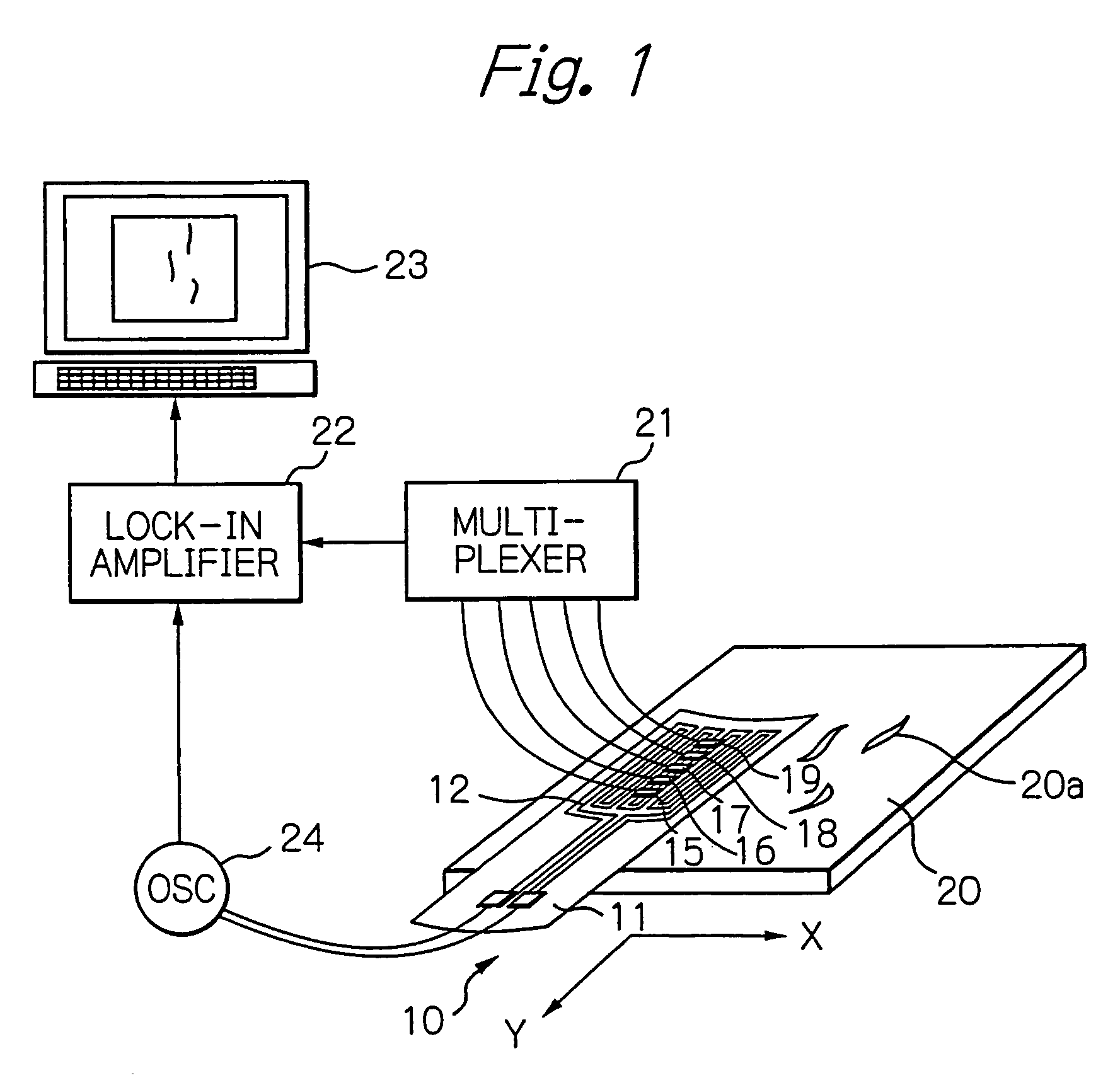
[0066]FIG. 1 shows a diagram schematically illustrating a configuration of an testing system using the eddy-current according to a preferred embodiment of the present invention,

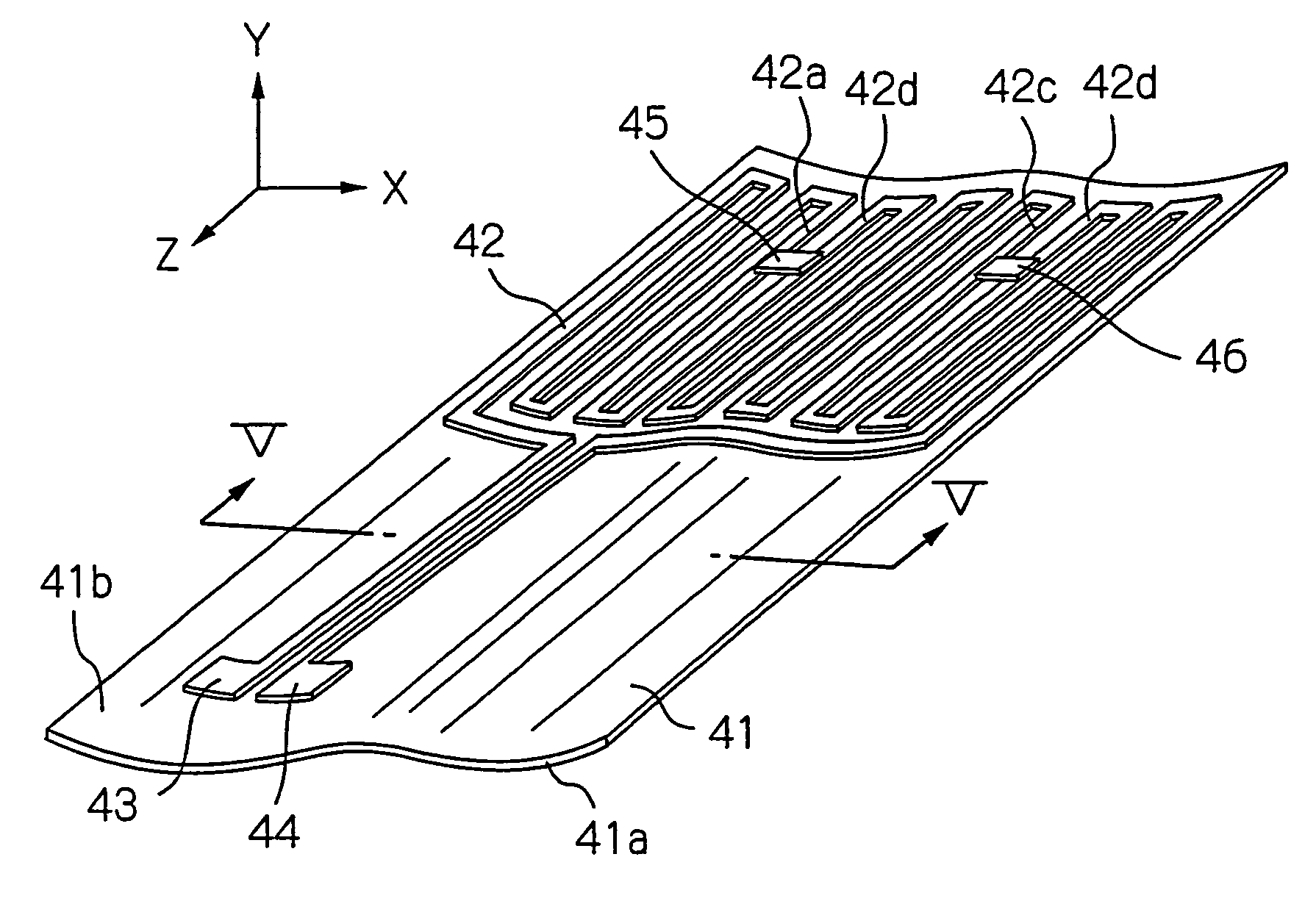
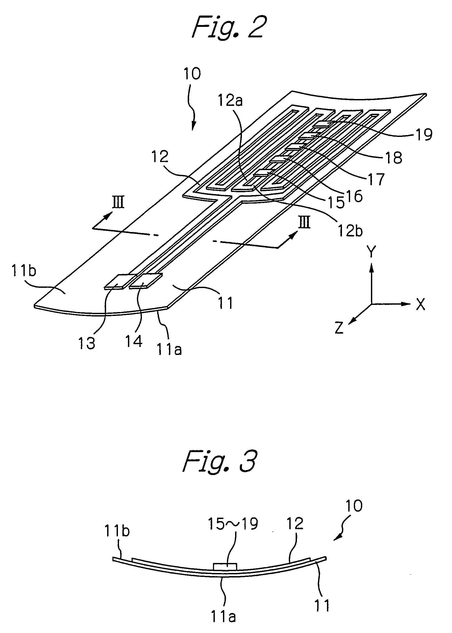
[0067]FIG. 2 shows a perspective view schematically illustrating a configuration of the ECT probe according to the embodiment in FIG. 1, and FIG. 3 shows a cross-sectional view taken along with line III—III in FIG. 2.

[0068]In these figures, reference numeral 10 indicates an ECT probe, 1 indicates its flexible substrate formed of an insulative material such as polyimide, 12 indicates a meander-type exciting coil including coil conductors formed as a planar pattern turned back on the opposite surface 11b to the measurement surface 11a of the substrate 1, 13 and 14 indicate a pair of electrode terminals formed on the substrate 1, which is connected electrically to both ends of the exciting coil 12, 15 to 19 indicate thin-film chips bonded on the exciting coil 12, each of which is mounted with a GMR element (eddy...


PUM


Abstract

An eddy-current probe according to the present invention comprises: a substrate having a first surface facing to a subject to be tested and a second surface opposite to said first surface; an exciting coil formed on the second surface, having a pair of current lines in parallel with each other through which exciting currents flow in opposite directions to each other during testing, for generating an alternate magnetic field applied to the subject by the exciting currents; and at least one eddy-current sensor positioned on a central axis between the pair of current lines on the second surface of the substrate, for detecting a magnetic field generated newly from the subject by an eddy-current induced by the alternate magnetic field. The substrate has a non-planar form having at least one convex-surface portion on the first surface, and the at least one eddy-current sensor is formed on at least one concave-surface portion formed on the second surface, which is corresponding to the at least one convex-surface portion.

Description

PRIORITY CLAIM[0001]This application is a divisional application of application Ser. No. 11 / 203,252, filed Aug. 15, 2005, which is a divisional application of application Ser. No. 10 / 938,541, filed Sep. 13, 2004 now U.S. Pat. No. 6,954,065.[0002]This application claims priority from Japanese patent application No.2003-326174, filed on Sep. 18, 2003, which is incorporated herein by reference.BACKGROUND OF THE INVENTION[0003]1. Field of the Invention[0004]The present invention relates to an eddy-current probe that is able to detect object's shapes, defects and so on nondestructively.[0005]2. Description of the Related Art[0006]Eddy-current testing (ECT) technique is frequently utilized for nondestructive testing of distorted surfaces of important metal machine parts used in a nuclear power plant, an airplane and so on, such as turbine blades, various pipes and airplane wings. Generally, such an ECT probe using the eddy-current includes mainly an exciting coil and a detector coil for d...

Claims


Application Information

Patent Timeline
IPC IPC(8): G01R33/12G01B7/00G01N27/72
CPCG01N27/9033G01N27/82G01N27/9006
Inventor SHOJI, SHIGERU
Owner TDK CORPARATION
Why Eureka
Try Eureka