Narrow band-pass tuned resonator filter topologies having high selectivity, low insertion loss and improved out-of-band rejection over extended frequency ranges

a resonator filter, narrow bandpass technology, applied in the direction of coils, electrical equipment, waveguide devices, etc., can solve the problems of high insertion loss, high ql, high insertion loss, etc., to achieve low insertion loss, high ql, and high ql.

Inactive Publication Date: 2006-07-18
ARRIS ENTERPRISES LLC
View PDF7 Cites 21 Cited by
  • Summary
  • Abstract
  • Description
  • Claims
  • Application Information

AI Technical Summary

Benefits of technology

[0025]It is an objective of a second embodiment of the present invention to achieve still higher values of QL, with low insertion loss and a steeper roll-off between the pass-band and the stop-band at both lower and higher frequencies, with the addition of only one additional component to the first embodiment.
[0026]It is an objective of a third embodiment of the present invention to achieve still higher values of QL, with low insertion loss and a steeper roll-off between the pass-band and t...

Problems solved by technology

The shortcomings of such filters are numerous for purposes of processing broadband signals in the VHF and UHF frequency bands, the most serious of which is that the lumped components (particularly the coil inductors) are highly susceptible to parasitic effects at frequencies much above 100 MHz.
Thus, such filters take up valuable space and make their cost of manufacture relatively high.
They are not, however, suitable for frequencies much below 150 MHz, because very large inductor values would be required for the resonators below that frequency.
Such inductors are impractical or impossible to construct.
Moreover, even at higher frequencies they are rather large mechanical structures (they require shielding both for proper operation and to reduce susceptibility to RF noise), which makes them relatively expensive to manufacture (even in high volumes).
They also are highly susceptible to environmental shock and drift, and they typically require an adjustment in value during the manufacturing process to make sure that they resonate accurately at the proper frequency.
Because the trace length increases as the desired resonant frequency decreases, however, such resonators are not suitable for anything other than UHF (i.e. between about 400 MHz and several GHz).
They become cost prohibitive for HF and VHF applications because the lengths of the transmission lines increase to a prohibitive size.
Even at 1 to 2 GHz, these implementations require trace lengths on the order of about 2 to 1 inches respectively, which is still quite large and consumes significant area.
Moreover, this would not scale well to manufacturing technologies of higher resolution (e.g. integrated circuits) because the length required to ac...

Method used


Image

  • Narrow band-pass tuned resonator filter topologies having high selectivity, low insertion loss and improved out-of-band rejection over extended frequency ranges
  • Narrow band-pass tuned resonator filter topologies having high selectivity, low insertion loss and improved out-of-band rejection over extended frequency ranges
  • Narrow band-pass tuned resonator filter topologies having high selectivity, low insertion loss and improved out-of-band rejection over extended frequency ranges

Examples


first embodiment

[0096]The improved response for the double-tuned resonator topology using microstrip inductance elements over the prior art implementation of the topology using prior art lumped inductor components (FIG. 5) is illustrated by comparison of the simulated output responses of FIGS. 9a and 9b (for the present invention) with the responses of FIGS. 6a and 6b (for the prior art). the present invention achieves a QL of about 25 (and thus a fractional bandwidth of about 4%) at a resonant frequency of 400 MHz, compared to a QL of about 6.5 (and a fractional bandwidth of about 15.5%) for the prior art at the same frequency. The out-of-band attenuation is also significantly improved.

[0097]Those of skill in the art will recognize the novelty and nonobvious use of microstrip transmission lines as effective inductor elements in magnetically coupled resonators, which is significantly distinctive over the prior use of microstrip transmission lines as resonators. The use of microstrip transmission li...

fourth embodiment

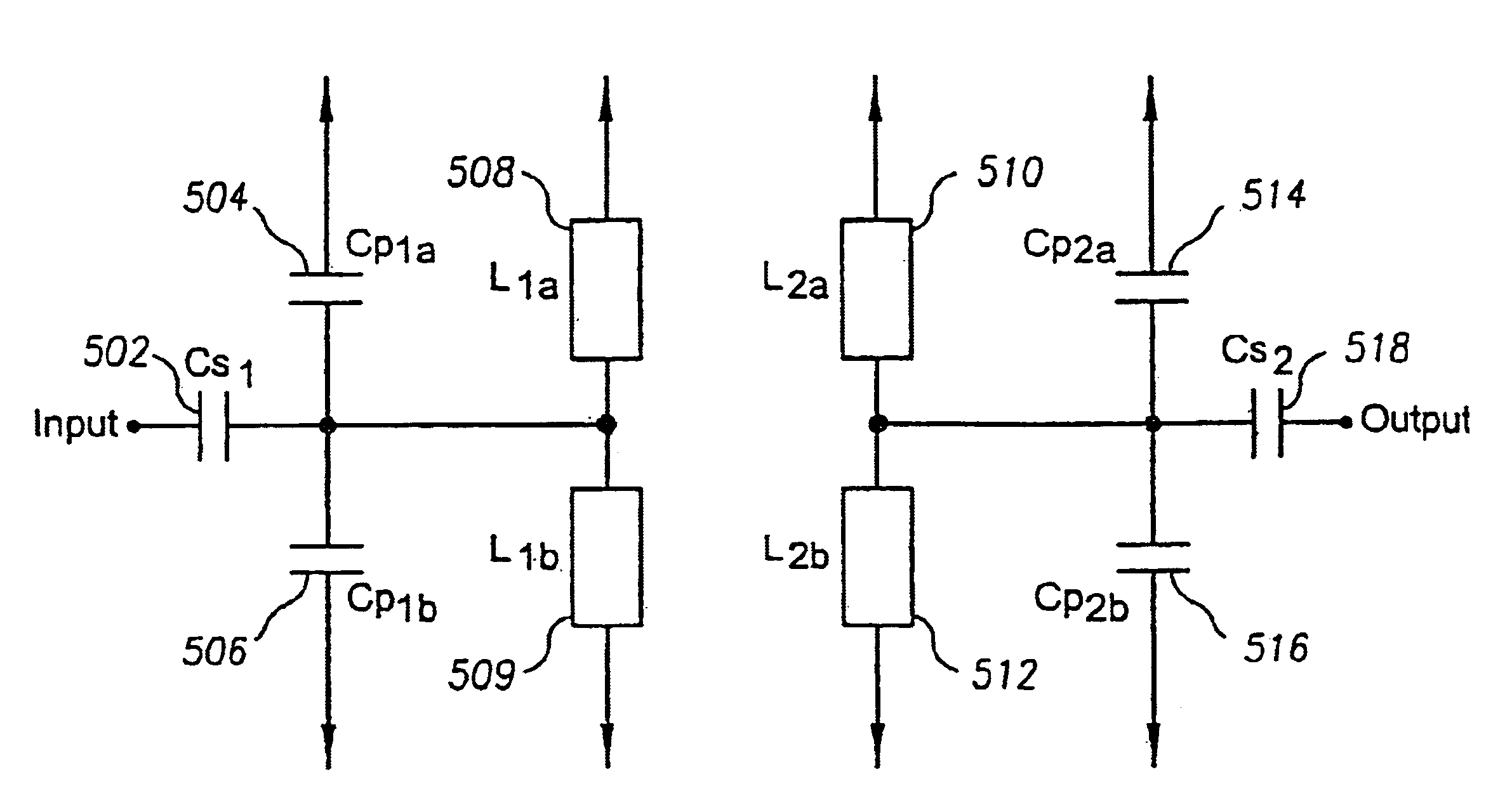
[0112]Thus, the invention is disclosed in FIG. 32a, in which each of the resonators of the original topologies (FIGS. 7 and 10a ) has a mirror image of itself coupled to its signal line as shown. This topology provides two very important features that permit its application to frequencies ranging from about 500 MHz and over 2 GHz. First, it permits the effective inductance values for each resonator to be reduced even further beyond the limits to which the metal strips can be shortened based on manufacturing tolerances. The inductive elements L1a 508 and L1b 509 of the input resonator and inductive elements L2a 510 and L2b 512 of the output resonator are in parallel with one another respectively, thus reducing the effective inductance of the input and output resonators by over 50 percent.

[0113]The ability to further reduce the inductance values permits parallel capacitors CP1a 504, CP1b 506 and CP2a 514, CP2b 516 to be increased in value as the frequency is increased to offset the de...


PUM


Abstract

A tuned resonator circuit topology is disclosed that permits implementation of narrow band-pass filters having high loaded Q and optimal coupling (for low insertion loss) using a parallel tuned resonator topology at frequencies in the 1 to 2 GHz range and beyond. The topology consists of a mirror image of the parallel tuned circuit about the signal line of a conventional parallel tuned circuit to effect a cancellation of virtually all of the induced currents between the inductive elements of the resonators. This reduction in induced currents reduces the magnetic coupling between the resonators, thereby offsetting the increase in overall coupling between the resonators as frequency increases, and thereby serves to maintain optimal coupling between the resonators as the frequency of operation increases. Moreover, the mirror image topology increases the parallelism between the inductive elements in the resonators, thereby decreasing the inductance values and permitting an increase in capacitance values. Increasing the capacitance values of the resonators effectively offsets the decrease in the loaded Q as frequency is increased. The topology works for any number of parallel resonators. As the resolution of the manufacturing process decreases (e.g. from printed circuit board to integrated circuit processes), the range of operating frequencies scales with the increase in resolution.

Description

[0001]This application is a continuation-in-part of U.S. application Ser. No. 09 / 039,988, filed Mar. 16, 1998 now issued as U.S. Pat. No. 6,215,374.BACKGROUND OF THE INVENTION[0002]1. Field of the Invention[0003]This invention relates to narrow band-pass tuned resonator filter topologies for advantageous application over high frequency (HF), very high frequency (VHF), ultra high frequency (UHF) and microwave bands, and more specifically to such topologies capable of maintaining over the frequency ranges of interest a high loaded Q for increased selectivity, optimal coupling to minimize insertion loss with improved out-of-band rejection, and which are relatively simple and inexpensive to manufacture with a high degree of repeatable accuracy.[0004]2. Background of the Related Art[0005]The processing of broadband multi-carrier signals presents a particularly rigorous and stringent context for signal processing circuitry such as filters. The base-band television signal for example, whic...

Claims


Application Information

Patent Timeline
IPC IPC(8): H03H7/09
CPCH01P1/203H03H7/1775H03H7/09H03H7/0123
Inventor PETROVIC, BRANISLAV A.
Owner ARRIS ENTERPRISES LLC
Why Eureka
Try Eureka