Method for avoiding an internal coking of an injection hole for injection holes in a multi-hole injection valve

a multi-hole injection valve and injection hole technology, applied in the direction of machines/engines, electric control, instruments, etc., can solve the problems of inability to drive steadily in partial load operation, inability to achieve uniform fuel distribution, and inability to handle large loads in stratified operation, etc., to achieve favorable efficiency

Inactive Publication Date: 2006-07-25
ROBERT BOSCH GMBH
View PDF10 Cites 9 Cited by
  • Summary
  • Abstract
  • Description
  • Claims
  • Application Information

AI Technical Summary

Benefits of technology

[0014]According to the present invention, by a subdivision of the injection pulse into a plurality of injection pulses, injector orifice internal coking of a fuel injector, e.g., of a multi-orifice fuel injector, may effectively be avoided. In addition, due to the split-up injection, combustion having a favorable efficiency sets in, which is shown by the exhaust gas temperature being clearly lower compared to when there is single injection.
[0016]According to the present invention, a second and each additional injection of fuel into the combustion chamber is able to reduce the deposits of the high-boiling fuel components on the inside of the spray orifices of the fuel injector. On account of the second injection, the inside contour of the spray orifice region is blown free of the deposit of fuel condensate that occurred before. Besides that, in response to a second injection pulse, the fuel is pressed into the injector since, for example, the fuel column in the fuel injector has to be injected against the compression pressure in the combustion chamber. This causes a saturated wall deposit of the fuel which does not have separation tendencies, whereby heat convection and valve inside cooling are greatly improved, and the separation of the fuel into highly volatile and difficultly volatile fuel components is prevented. The fuel is injected with its additives almost completely into the combustion chamber. Due to the suppressed separation, no partially reacted combustion residues then form on the inside of the spray orifices.
[0021]The method according to the present invention may be used for avoiding injector orifice internal coking of spray orifices of fuel injectors in an internal combustion engine.

Problems solved by technology

In the case of both combustion methods there is no uniform fuel distribution, but rather a stratified charge.
Greater loads, however, may not be handled by stratified operation.
Internal combustion engines having direct fuel injection, in partial-load operation may not be driven steadily in thermodynamically optimal, throttle-free, quality-controlled stratified operation.
Displacing the injection time into the compression stroke, in conjunction with extreme air intake throttling, causes very great soot emission, and is therefore not used in practice.
Combustion of a fuel / air mixture, at great underpressure and having stoichiometric mixture composition, has great wall heat losses from heating up the combustion chamber walls, and, consequently, also the injection elements.
On account of the heat of combustion, high-boiling deposits are created at the inner walls of the spray orifices, which are no longer able to be completely burned.
Thereby, the quantity of the postinjection is tightly limited time-wise.
However, in combustion chambers including flat pistons, one may inject in the range of the top piston speed, since in this phase the aspirated air reaches its greatest flow speed, and thus the mixing of fuel and air would be most intensive.

Method used


Image

  • Method for avoiding an internal coking of an injection hole for injection holes in a multi-hole injection valve
  • Method for avoiding an internal coking of an injection hole for injection holes in a multi-hole injection valve
  • Method for avoiding an internal coking of an injection hole for injection holes in a multi-hole injection valve

Examples


Embodiment Construction

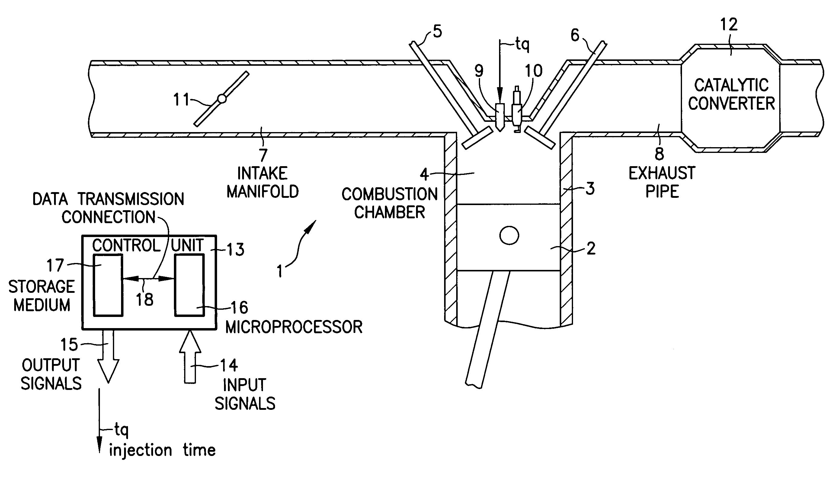
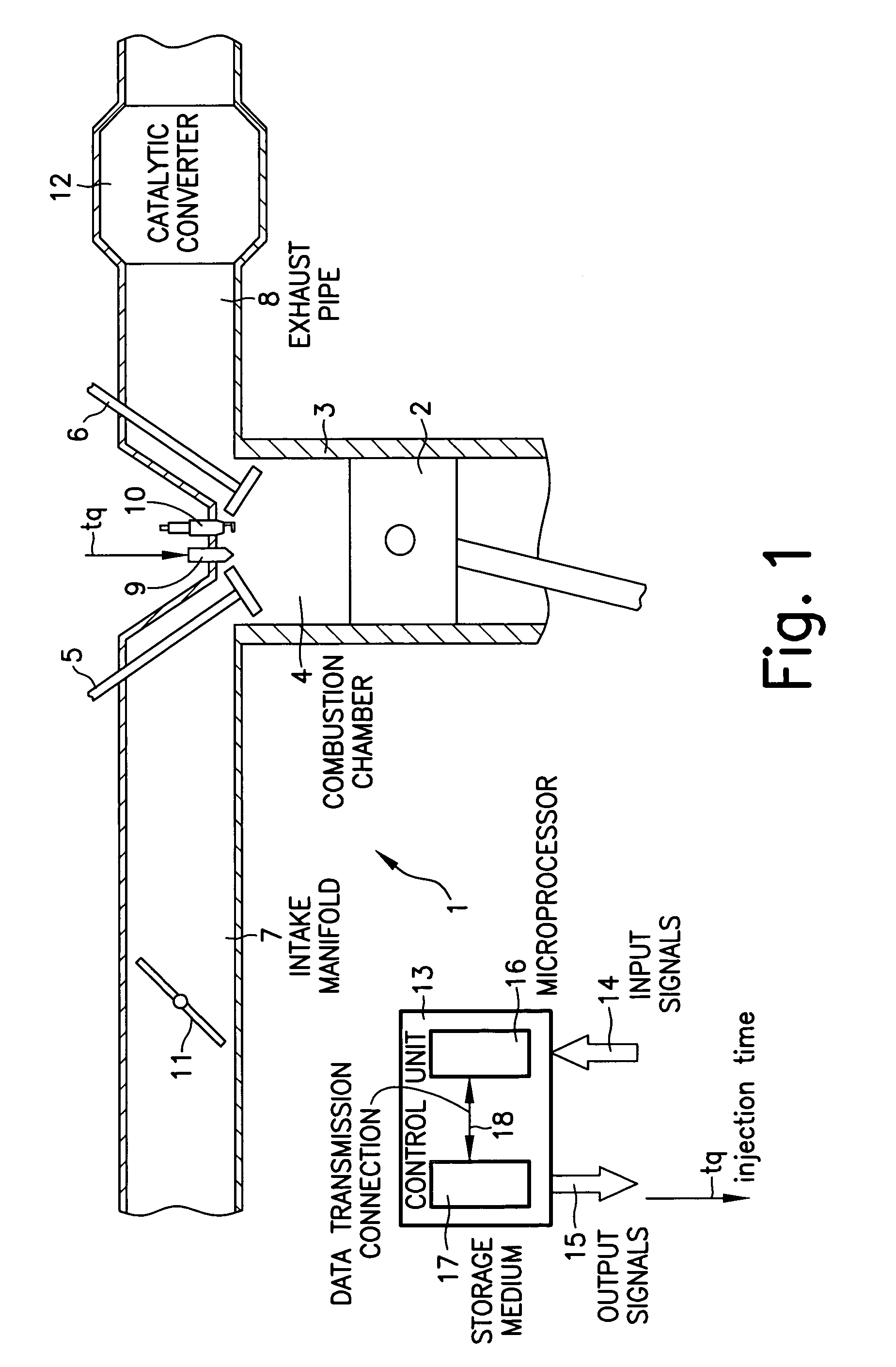
[0031]FIG. 1 shows an internal combustion engine 1 of a motor vehicle, in which a piston 2 may be moved back and forth in a cylinder 3. Cylinder 3 is provided with a combustion chamber 4, whose boundary is marked by, among other things, piston 2, an intake valve 5, and an exhaust valve 6. An intake manifold 7 is connected to intake valve 5, and an exhaust pipe 8 is connected to exhaust valve 6.

[0032]In the region of intake valve 5 and of exhaust valve 6, there project into combustion chamber 4 a fuel injector 9 (a so-called injector) configured as a multi-orifice fuel injector and a spark plug 10. Fuel is able to be injected into combustion chamber 4 via injector 9. The fuel in combustion chamber 4 may be ignited by spark plug 10.

[0033]A rotatable throttle valve 11, through which air may be supplied to intake manifold 7, is accommodated in intake manifold 7. The quantity of supplied air is a function of the angular setting of throttle valve 11. In exhaust pipe 8 a catalytic converte...


PUM


Abstract

A method for avoiding an injector orifice internal coking of the spray orifices of a multi-orifice fuel injector of a direct injection internal combustion engine, e.g., of a motor vehicle, is provided. Fuel is injected into a combustion chamber of the internal combustion engine by multiple injections. The fuel is injected by a first main injection during the intake stroke and by a subsequent postinjection during the compression stroke before the ignition time. Thereby, during a long operation of the internal combustion engine, especially in a homogeneous operation, the injection time does not have to be continually increased in order to compensate for the increasingly shrinking cross section of the spray orifices.

Description

FIELD OF THE INVENTION[0001]The present invention relates to a method for operating a direct injection internal combustion engine, e.g., of a motor vehicle.BACKGROUND INFORMATION[0002]Direct injection internal combustion engines, in which fuel is injected directly into the combustion chambers of the internal combustion engine, are known in the art. A direct injection internal combustion engine may be operated in different operating modes, for instance, in a stratified operation or a homogeneous operation. Stratified operation is used especially for small loads, whereas homogeneous operation comes into use for greater loads on the internal combustion engine.[0003]In stratified operation, the fuel is injected into the combustion chamber during a compression stroke of the internal combustion engine in such a manner that, at the time of ignition, there is a fuel cloud in the immediate surroundings of a spark plug. This injection may proceed in different manners. Thus, it is possible tha...

Claims


Application Information

Patent Timeline
Patent Type & Authority Patents(United States)
IPC IPC(8): F02D41/40F02M61/18F02D41/04F02D41/34F02D45/00F02M45/02F02M65/00
CPCF02D41/402F02D41/3023Y02T10/44F02M45/02F02M65/008F02D2041/389Y02T10/40F02D41/40
Inventor BRITSCH, HEINZWUERFEL, GERNOT
Owner ROBERT BOSCH GMBH
Why Eureka
Try Eureka