Encapsulated filter cartridge

a filter cartridge and cartridge body technology, applied in the direction of membranes, filtration separation, separation processes, etc., can solve the problems of insufficient efforts of individuals and organizations, insufficient on-site water filters, and significant amounts of harmful or offensive chemicals in drinking or tap water, and achieve the effect of convenient disconnection

Inactive Publication Date: 2006-07-25
3M INNOVATIVE PROPERTIES CO
View PDF21 Cites 98 Cited by
  • Summary
  • Abstract
  • Description
  • Claims
  • Application Information

AI Technical Summary

Benefits of technology

[0023]The inventors of the present disclosure have resolved many of the problems associated with the filter assemblies described above, by employing a permanently encapsulated filter cartridge having a composite filter assembly that includes a carbon block filter element to remove particulate matter and absorb chemical contaminants and a microporous filter element, e.g., a hollow microporous fiber subassembly, a pleated filter element, or a different structure capable of performing a similar function, to remove microorganisms and / or particulate matter from the filtrate passing through the filter cartridge. In contrast to the prior art filtration devices, the encapsulated filter cartridge constructed in accordance with the present disclosure is disposable and may be easily disconnected and discarded as a unit. This is particularly important where the interior chamber of the filter cartridge must be maintained free of contamination, such as in medical or pharmaceutical applications.
[0024]Among the advantages of the disposable filter cartridge according to the present disclosure are its increased ease of manufacturing and superior performance characteristics, such as capacity for effective removal of chemical contaminants, particulate matter and microorganisms, while maintaining relatively long life time and relatively low pressure drop. In addition, the disposable filter cartridge according to the present disclosure need not be opened in order to replace the filter assembly, but is removed and discarded as a unit. This advantageous feature helps avoid contamination of the appliance and the hands of the person manipulating the filter cartridge by stray carbon and other particles from the filter and promotes air- or fluid-tight operation of the filter cartridge. Furthermore, this feature facilitates contamination-free operation of the filter cartridge itself.
[0025]Among the advantages of the filter assembly having a microporous filter element disposed upstream of the carbon block filter element is its capability of retaining microorganisms before they can enter the carbon block element where they can grow, multiply and eventually colonize the filter cartridge. In addition, when the carbon block element is located downstream of the microporous element, any undesirable odor or taste generated in the microporous element, e.g., due to the presence of microorganisms, may be subsequently removed by the carbon block element.

Problems solved by technology

In most areas of the world, drinking or tap water contains significant amounts of harmful or offensive chemicals, suspended particulate matter, and microorganisms.
Although municipal water treatment plants attempt to address this problem, many individuals and organizations find such efforts insufficient and utilize on-site water filters.
Nonetheless, most carbonaceous filter elements are not fine enough to remove bacteria, viruses or other microorganisms.
Due to the use of granulated activated carbon in the absorbent module, this water-purification device suffers from various disadvantages, such as the setting of the carbon particles over time, leading to decreased filtration efficiency, and channeling of the filtrate in the sorbant bed due to unintended shock or vibration, leading to a decrease in the reliability of the filtration system.
This arrangement, in part due to the use of the flow control tube, requires high fluid pressures for filtration and results in high fluid pressure drop in the filtration process.
In addition, while filtration may be improved by increasing the path of the water through the carbon medium, U.S. Pat. No. 5,102,542 fails to take into account that filtration rate efficiency of the porous hollow fibers and filtration life of the assembly are significantly reduced by the reduction of the exposed surface area of the fibers available for radial filtration.
Furthermore, although U.S. Pat. No. 5,102,542 purports to provide an improved procedure for removal of the filter element from its housing, the process remains rather complicated.
For example, coating the outer surface of the membrane with a layer of activated carbon inhibits porosity of the membrane, so that the coated membrane becomes incapable of relatively coarse filtration.
In addition, the pre-coat design may result in insufficient depth and non-uniform thickness of the carbon layer or, possibly, even in bare spots on the membrane.
The pleated membranes for use in the filtering apparatus, described in U.S. Pat. No. 6,136,189, are not capable of retaining particles smaller then about 1 micron.
These structural shortcomings result in decreased efficiency of this filter and in the lack of quality of the resultant product.
The water filter described in U.S. Pat. No. 5,707,518 does not include a microporous element for removing microorganisms and suffers from the need to open the housing in order to replace the filter element.
Although references discussed above disclose composite filter elements incorporated into filtration devices, they do not teach or suggest, alone or in combination, a disposable encapsulated filter cartridge, nor do they provide a filter cartridge assembly suitable for inclusion and effective operation as part of a disposable encapsulated filter cartridge.
As explained above, using such medium in a water filter results in various disadvantages as compared to the present disclosure, which teaches, among other things, the use of a carbon block filter element to reduce chemical contamination and particulate matter within a fluid stream.

Method used


Image

  • Encapsulated filter cartridge
  • Encapsulated filter cartridge
  • Encapsulated filter cartridge

Examples


Embodiment Construction

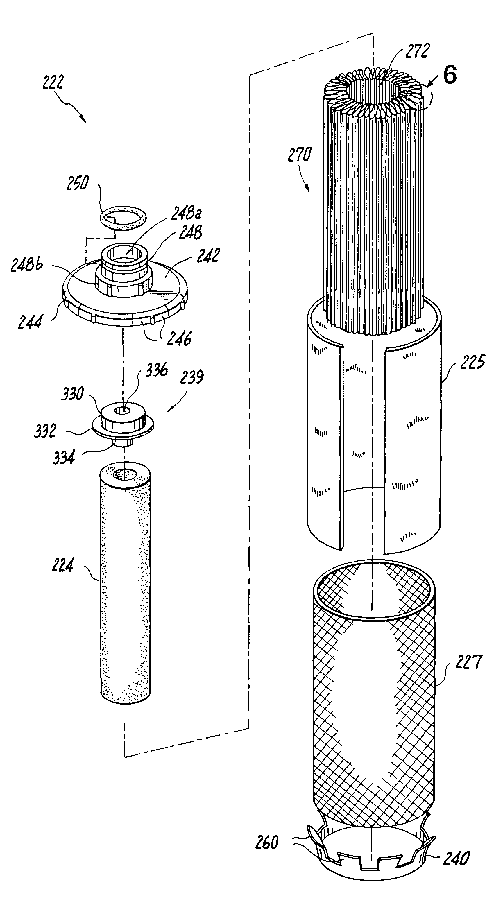
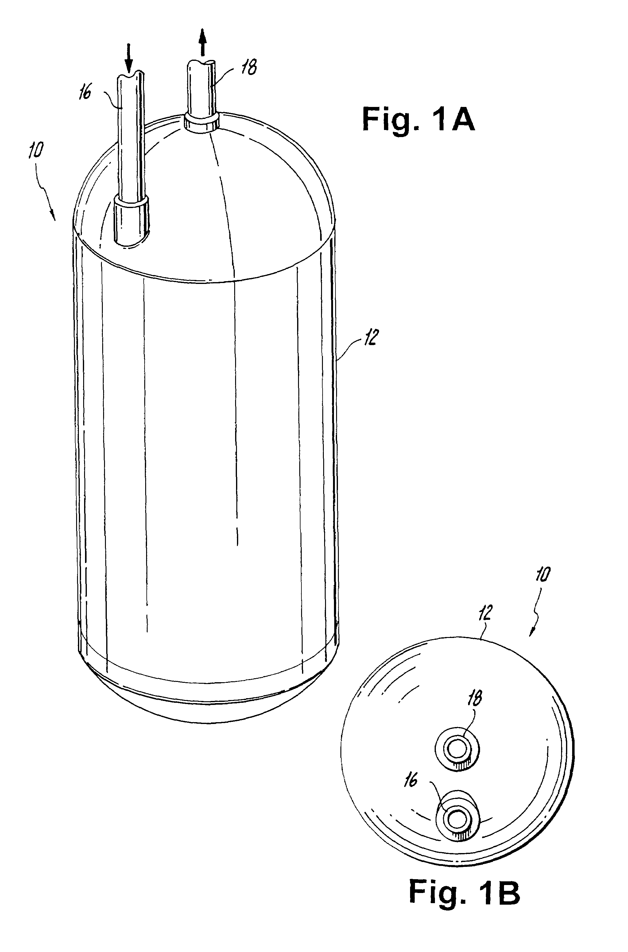
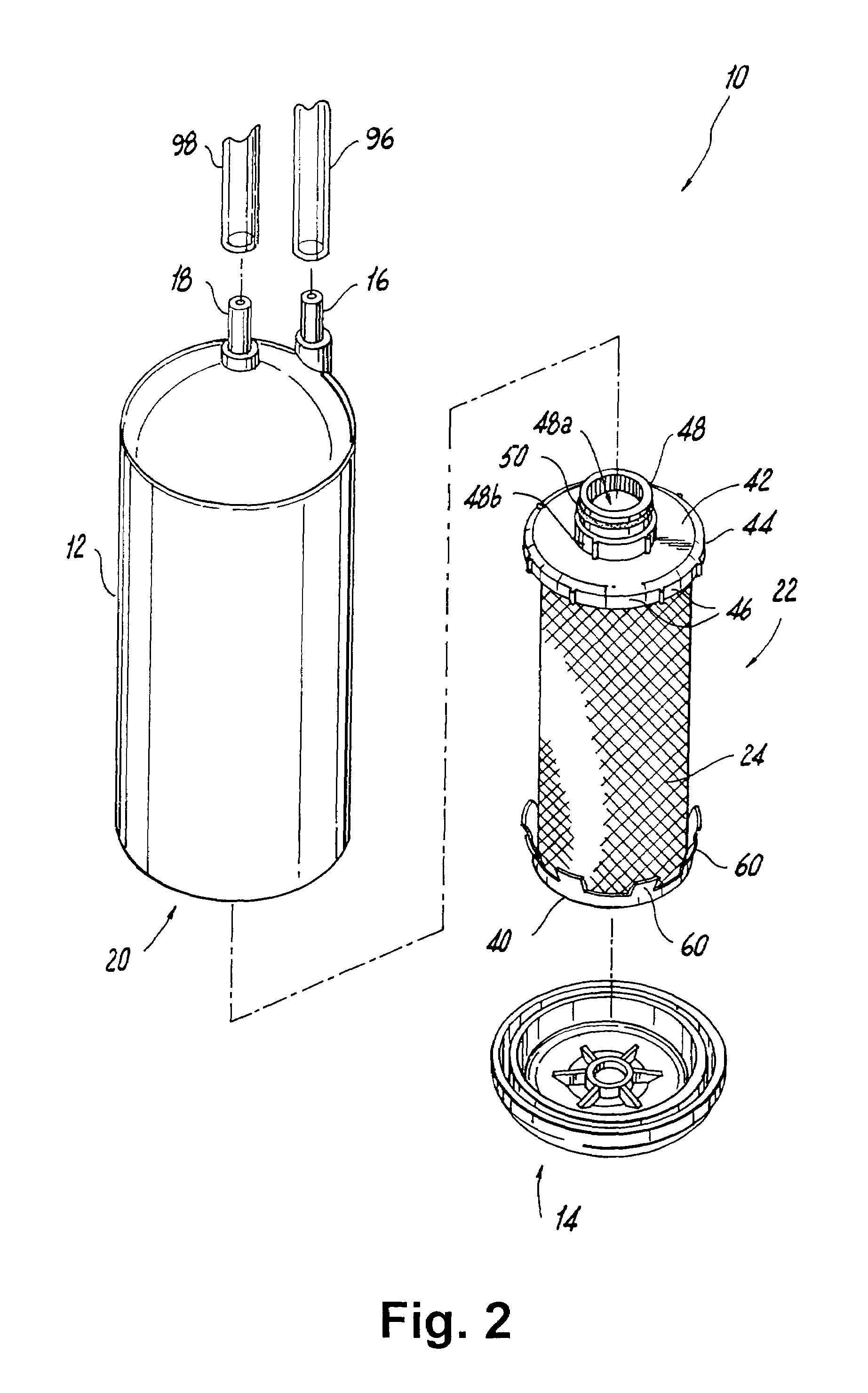
[0046]Referring now to the drawings, wherein like reference numerals identify similar structural elements of the filtration device described herein, there is illustrated in FIG. 1A a disposable encapsulated filter cartridge constructed in accordance with an exemplary embodiment of the subject disclosure and designated generally by reference numeral 10. As illustrated in FIGS. 2, 4 and 7, the filter cartridge 10,110,210 includes a sump 12,112,212 having an interior chamber 20,120,220 for supporting a filter assembly 22,122,222 and a closure cap 14,114,214 at the bottom end thereof for permanently enclosing the filter cartridge within the sump. The closure cap 14,114,214 is preferably spun welded to the bottom end of the sump 12,112,212. Other ways in which the closure cap 14,114,214 may be joined to the bottom end of the sump 12,112,212 may include ultrasonic welding, hot plate welding, induction welding, overmolding and mechanical securement means.

[0047]The sump 12,112,212 has an in...


PUM

PropertyMeasurementUnit
pore sizeaaaaaaaaaa
thicknessaaaaaaaaaa
pore sizeaaaaaaaaaa

Abstract

An encapsulated filter cartridge is disclosed, which includes a filter assembly including a carbon block filter element and a microporous filter element. The filter cartridge has a permanently sealed sump defining an interior chamber configured to accommodate the filter assembly, the sump having an inlet for permitting unfiltered fluid to enter the interior chamber for communicating with the radially outer surface of the filter assembly and an outlet for permitting filtered fluid to exit the interior chamber from the axial portion of the filter assembly. The microporous filter element of the filter assembly may include a hollow fiber subassembly housed within the axial cavity of the carbon block element, said fiber subassembly including a plurality of hollow microporous fibers, or a pleated filter element surrounding the radially outer surface of the carbon block element.

Description

RELATED APPLICATION[0001]The subject application claims the benefit of priority of the Provisional U.S. Patent Application Ser. No. 60 / 374,067, filed on Apr. 19, 2002, which is hereby incorporated by reference in its entirety.BACKGROUND OF THE INVENTION[0002]1. Field of the Invention[0003]The subject invention relates to a fluid filtration device, and more particularly, to an encapsulated filter cartridge having a permanently sealed sump, configured to accommodate a filter assembly. The filter assembly includes a carbon block filter element and a microporous filter element. The microporous filter element of the filter assembly may be, for example, a hollow microporous fiber subassembly housed within the axial cavity of the carbon block element or a pleated filter element surrounding the radially outer surface of the carbon block filter element.[0004]2. Background of the Related Art[0005]In most areas of the world, drinking or tap water contains significant amounts of harmful or offe...

Claims


Application Information

Patent Timeline
Patent Type & Authority Patents(United States)
IPC IPC(8): B01D25/00B01D24/00B01D25/02B01D27/04B01D27/06B01D27/14B01D29/07B01D63/02B01D63/14C02F1/44B01D36/00B01D61/18B01D61/20B01D63/06B01D65/00B01D69/00B01D69/08B01D69/12C02F1/00C02F1/28
CPCB01D27/06B01D61/18B01D61/20B01D63/024B01D63/067B01D65/00C02F1/003B01D36/001B01D27/148B01D2313/90B01D2201/291C02F1/283C02F1/444C02F2201/006B01D2313/21B01D2313/04
Inventor BASSETT, LAURENCE W.BLAZE, MARTINHAMLIN, THOMAS
Owner 3M INNOVATIVE PROPERTIES CO
Why Eureka
Try Eureka