Method for actively controlling the gram load on a disk drive suspension assembly

a technology of suspension assembly and gram load, which is applied in the direction of piezoelectric/electrostrictive transducers, instruments, record information storage, etc., can solve problems such as piezoelectric materials

Inactive Publication Date: 2006-08-01
HUTCHINSON TECH
View PDF61 Cites 61 Cited by
  • Summary
  • Abstract
  • Description
  • Claims
  • Application Information

AI Technical Summary

Benefits of technology

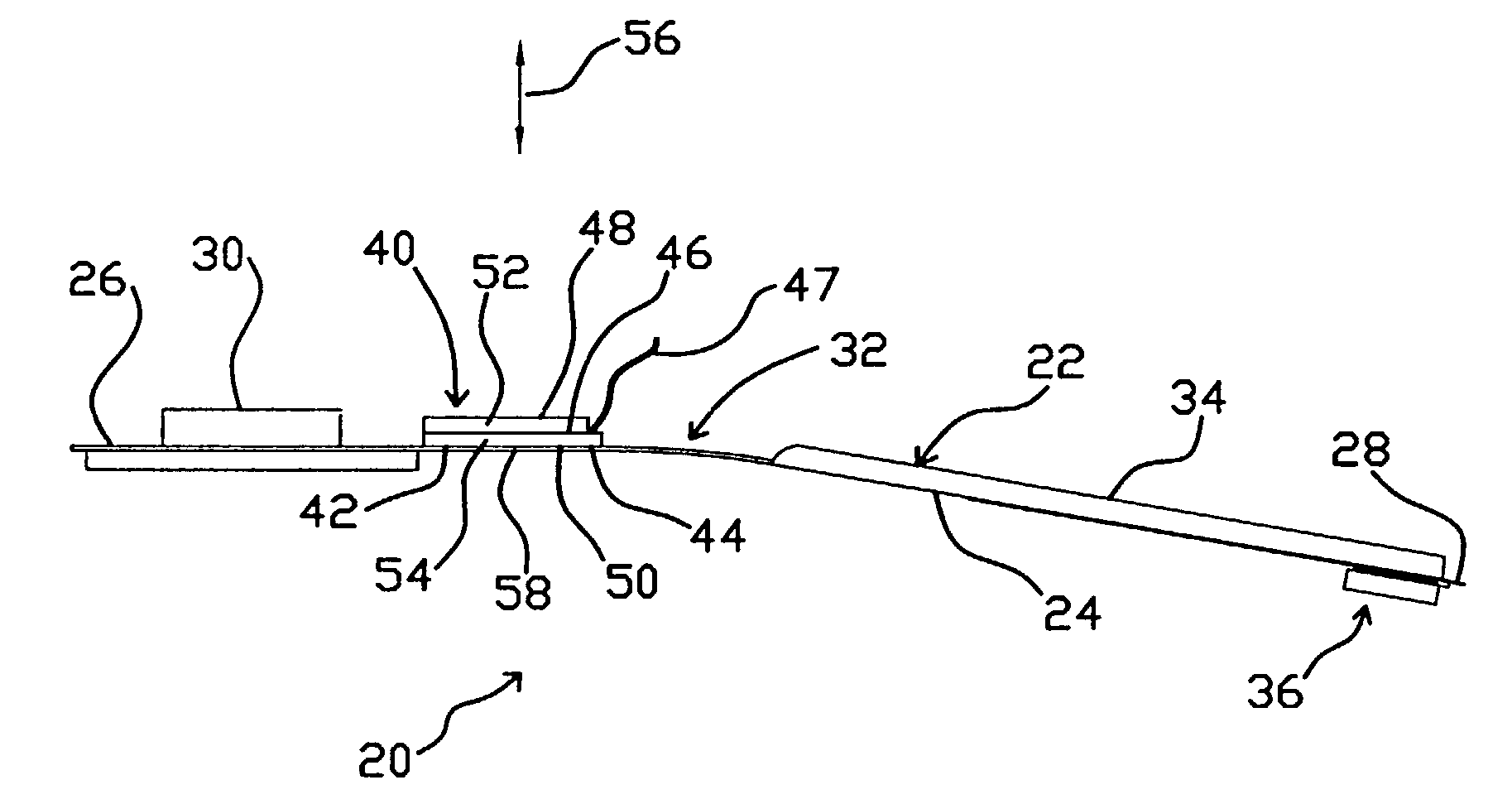
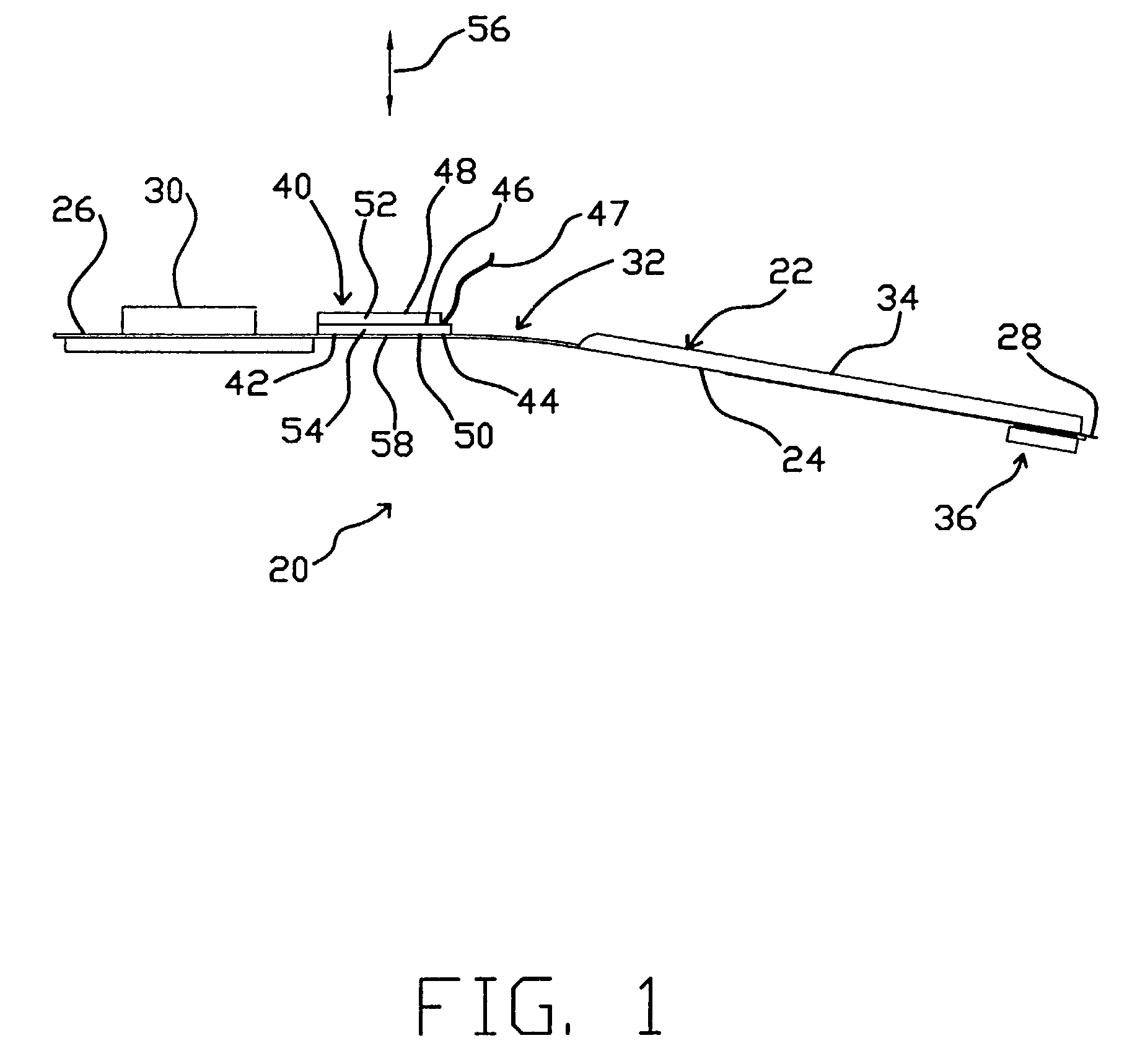
[0014]In one embodiment, the load beam may include a compliant region located between the first and second attachment locations for the piezoelectric actuator. Consequently, the piezoelectric actuator in an unactuated state supports a portion of the gram load. By arranging the multi-layer piezoelectric to span across the compliant region, a greater range of motion and a greater range of gram loading can be achieved. Compliant region refers to a partial etch, a hole, a recess, a narrowing of the load beam, one or more lines of weakness extending generally laterally across load beam, or other features in the load beam that create a location of flexibility greater than elsewhere along the load beam.
[0016]The multi-layer piezoelectric actuator can be used to determine precisely the flying height of the read / write heads on the disk drive suspension. Moreover, the gram load can be changed with changing drive conditions. The multi-layer piezoelectric actuator can eliminate the need for an active head lifter and landing zones on the fixed disk, while protecting the read / write heads during periods of inactivity. Since the layers of the multi-layer act as both actuators and transducers, the various layers produce a voltage when deflected. In one embodiment, these voltages are extracted to dampen gram changing vibrations and deflections. In another embodiment, the extracted voltages can be actively counteracted to reduce gram changing vibrations.

Problems solved by technology

Since the piezoelectric material of the '720 patent is limited to compression and expansion forces, it must be attached directly to the surface of the load beam.

Method used


Image

  • Method for actively controlling the gram load on a disk drive suspension assembly
  • Method for actively controlling the gram load on a disk drive suspension assembly
  • Method for actively controlling the gram load on a disk drive suspension assembly

Examples


example 1

[0048]Example 1 examined the gram load to applied voltage for the head suspension with the load bearing, multi-layer piezoelectric actuator.

[0049]The wires were soldered to the top surface and the stepped surface of the piezoelectric actuator. The base of the suspension and the top surface of the piezoelectric actuator were grounded, and voltage was supplied to the stepped middle electrode.

[0050]Voltage to the piezoelectric actuator was applied in 5 volt increments. In the first test, the voltage was applied from zero to +30 volts and then stepped to −30 volts and back to 0 volts. At each 5 volt increment, the gram was recorded. FIG. 5 shows a graph of the measured gram load versus applied voltage with a gram load ranging between about 1.67 grams and about 2.33 grams. The sensitivity of the gram-to-voltage calculated from the slope of the curve is 0.011 grams / volt.

example 2

[0051]Example 2 examined the gram load to applied voltage for the head suspension with the load bearing, multi-layer piezoelectric actuator.

[0052]Voltage to the piezoelectric actuator was applied in 5 volt increments. In the second test the voltage was applied from zero to +50 volts and then stepped to −50 volts. At each 5 volt increment, the gram load was recorded. FIG. 6 shows a graph of the measured gram versus applied voltage with a gram load ranging between about 1.42 grams and about 2.66 grams. The sensitivity of the gram-to-voltage calculated from the slope of the curve is 0.0124 grams / volt. The sensitivity of gram load-to-voltage is dependent on the piezoelectric actuator and suspension design. A head suspension could be designed for a particular sensitivity.

[0053]FIGS. 5 and 6 show some hysteresis in the curves of gram load versus applied voltage. Hysteresis is inherent in some piezoelectric materials. Use of a charge control system, instead of voltage control system, has t...

example 3

[0055]Example 3 examined the gram load and sensitivity of the head suspension with the load bearing, multi-layer piezoelectric actuator.

[0056]To determine the accuracy to which the gram load of the head suspension could be controlled, gram load levels of 1.75 grams and 2.25 grams were chosen as target values. To start the test, the nominal gram level was measured at 0 applied volts. Voltage was then slowly applied until the target gram load was met. The voltage at the target gram load was then recorded. Results of the test are shown in Table 1.

[0057]

TABLE 1Gram Load at 0Attained GramTarget Gram LoadVoltsLoadApplied Voltage1.75 grams2.03 grams1.75 grams−26 volts2.25 grams2.05 grams2.25 grams  21 volts

[0058]Example 3 shows that the present head suspension can control the gram load to within 0.01 grams accuracy, or a factor of 10 more accurately than conventional gram loading techniques. Gram levels of 2.25 and 1.75 grams were achieved by simply increasing or decreasing the voltage unt...


PUM

PropertyMeasurementUnit
thickaaaaaaaaaa
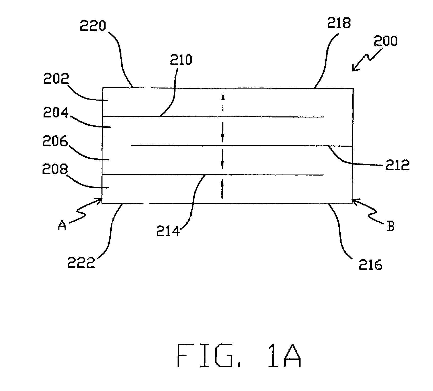
thickaaaaaaaaaa
thickaaaaaaaaaa

Abstract

A method and apparatus for actively controlling the gram load on a disk drive suspension assembly and to a disk drive using the present disk drive suspension assembly. The gram load can be actively changed by changing the applied voltage to one or more multi-layer piezoelectric actuators attached to the head suspension. The active gram control system allows the gram load to be changed on a non-permanent basis and to control the gram load to a much finer scale than can be accomplished using conventional techniques. By attaching the first and second ends of the piezoelectric actuator to discrete locations on the load beam, while the portion of the piezoelectric actuator between the first and second ends remains unattached to the load beam, a force non-parallel to the load beam can be applied to the head suspension.

Description

CROSS-REFERENCE TO RELATED APPLICATION[0001]This application is a divisional of U.S. application Ser. No. 09 / 342,931, filed Jun. 29, 1999, now U.S. Pat. No. 6,501,625, and entitled “Disk Drive Suspension With Multi-Layered Piezoeletric Actuator Controlled Gram Load.”FIELD OF THE INVENTION[0002]The present invention relates to a method and apparatus for actively controlling the gram load on a disk drive suspension assembly and a disk drive using the present disk drive suspension assembly.BACKGROUND OF THE INVENTION[0003]Head suspension assemblies are commonly used in rigid magnetic disk drives to support magnetic heads in close proximity to the rotating disk surfaces. Head suspension assemblies of this type typically include an air bearing head slider assembly mounted to a suspension. The suspension includes a load beam having a mounting region on its proximal end and a gimbal or flexure on its distal end. When incorporated into a disk drive, the mounting region is mounted to an actu...

Claims


Application Information

Patent Timeline
Patent Type & Authority Patents(United States)
IPC IPC(8): G11B5/127H04R31/00G11B21/21G11B5/48G11B5/55G11B21/10
CPCG11B5/4846G11B5/5552Y10T29/42Y10T29/49027Y10T29/49025Y10T29/4913Y10T29/4903G11B5/4873
Inventor BOISMIER, DENNIS A.HEFFELFINGER, JASON R.
Owner HUTCHINSON TECH
Why Eureka
Try Eureka