Integrated front end antenna

a front end antenna and integrated technology, applied in the structure of elongated active elements, resonant antennas, radiating elements, etc., can solve the problems of increasing the antenna, even at a quarter wavelength, not being suitable for use with certain communications devices, adding cost and additional power loss,

Active Publication Date: 2006-08-01
SKYCROSS INC
View PDF12 Cites 66 Cited by
  • Summary
  • Abstract
  • Description
  • Claims
  • Application Information

AI Technical Summary

Problems solved by technology

The resulting larger antenna, even at a quarter wavelength, may not be suitable for use with certain communications devices, especially portable and personal communications devices intended to be carried by a user.
The resistive component results from antenna radiation and ohmic losses.
Connecting an antenna to other communications components presents several physical and electrical interface challenges, whether the antenna is operative with spatially proximate communications components such as in a portable communications device, or physically distant from these components such as when mounted on an antenna mast above the earth's surface.
Unfortunately, the added matching components add cost and additional power loss, resulting in unrecoverable signal losses to heat in the matching components.
In addition to the electrical impedance matching, physical interface issues are important whenever an antenna is installed proximate other components of the communications device.
The transmission line connecting the components must be properly routed, and there are also component shielding issues to consider.
These design concerns add cost and complexity to the design process, and also to the cost of debugging the device to resolve problems caused by unexpected component interactions.
The same issues of physical and electrical interfacing are present in radio frequency transmitting and receiving installations utilizing a mast-based antenna connected via a transmission line to grou...

Method used


Image

  • Integrated front end antenna
  • Integrated front end antenna
  • Integrated front end antenna

Examples


Embodiment Construction

[0056]Before describing in detail the particular antenna and associated communications components in accordance with the present invention, it should be observed that the present invention resides primarily in a novel and non-obvious combination of elements. So as not to obscure the disclosure with details that will be readily apparent to those skilled in the art, certain conventional elements and steps have been described and illustrated with lesser detail, while other elements and steps pertinent to understanding the invention have been described and illustrated in greater detail.

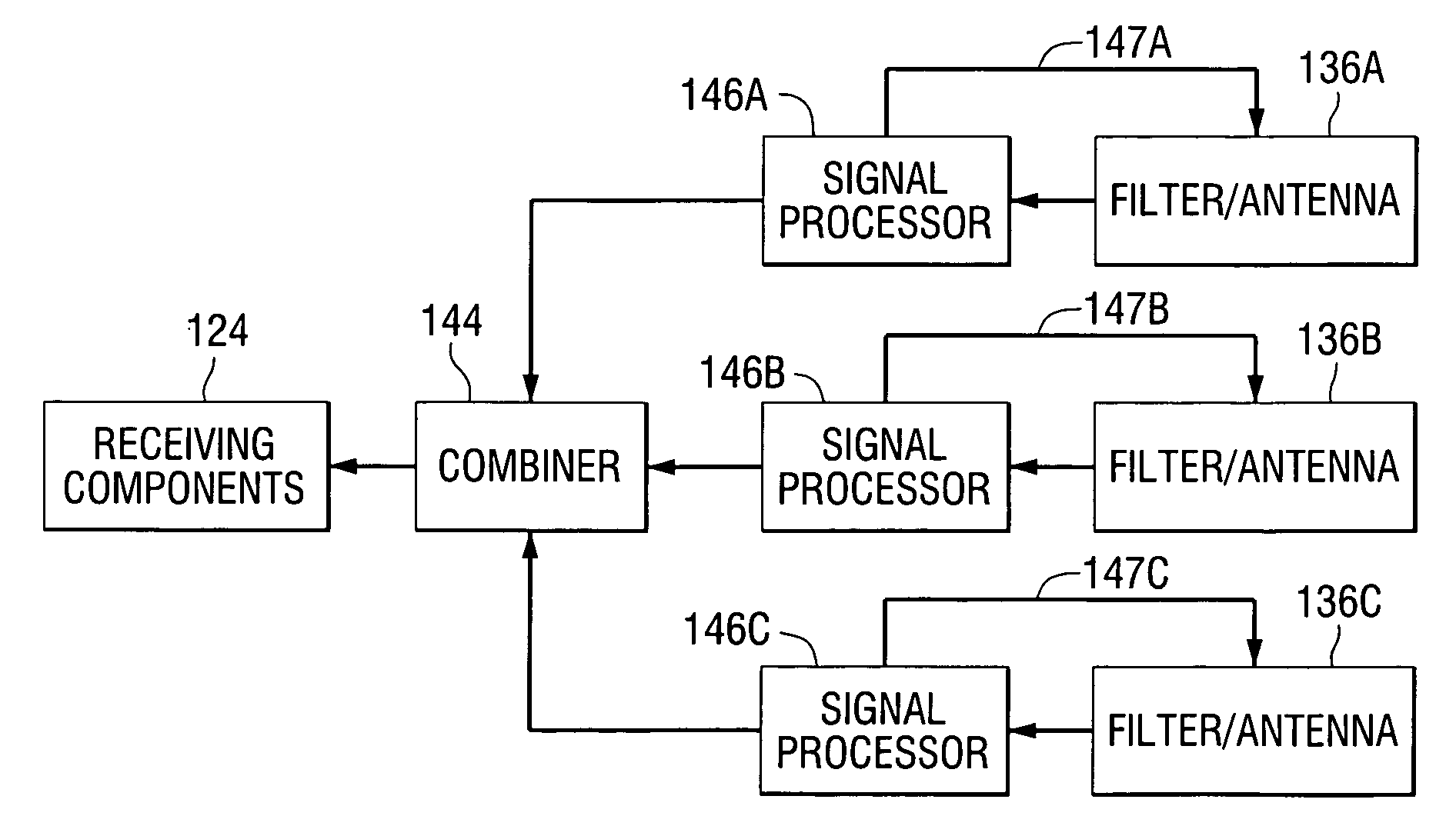
[0057]Integration of the antenna with certain front-end components as taught by the present invention can provide advantages in both amplifier power efficiency and antenna performance. Integration can also provide a cost advantage during product design and test due to elimination of certain component placement and interaction issues. The integration can include the antenna and the filter (in the receiving...


PUM


Abstract

A radio frequency transmitting and receiving apparatus comprising a filter and an antenna, wherein the input reactance of the antenna is substantially equal in magnitude and opposite in sign to the output reactance of the filter. This reactance relationship permits the antenna and filter to be collocated and avoids transformation of the input and output impedances to the conventional 50 ohms such that the filter and antenna can be connected with a conventional 50 ohm transmission line.

Description

[0001]This application claims the benefit of the provisional patent application entitled Integrated Front End Antenna filed on Feb. 26, 2003, and assigned application number 60 / 450,191. This application further claims the benefit of the non-provisional patent application entitled Antenna Including Intergrated Filter, files on Feb. 4, 2002 assigned application Ser. No. 10 / 066,937; which has been abandoned, which claims the benefit of the provisional application filed on Feb. 2, 2001 and assigned application number 60 / 266,245.FIELD OF THE INVENTION[0002]The present invention is directed generally to an antenna for transmitting and receiving electromagnetic signals, and more specifically to an antenna integrated with certain components for receiving and transmitting the electromagnetic signals via the antenna.BACKGROUND OF THE INVENTION[0003]It is known that antenna performance is dependent on the size, shape, and material composition of constituent antenna elements, as well as the rel...

Claims


Application Information

Patent Timeline
IPC IPC(8): H01Q11/12H01Q1/36H01Q5/00H01Q9/40H01Q9/42H01Q21/30
CPCH01Q1/36H01Q21/30H01Q9/42H01Q9/40
Inventor CAIMI, FRANK M.FARRAR, JOHN CHARLESGREER, KERRY LANETHURSBY, MICHAEL H.INNIS, DONALD A.
Owner SKYCROSS INC
Why Eureka
Try Eureka