
System for synchronizing communications system components coupled via a communications network

a communication system and communication system technology, applied in data switching networks, multiplex communication, generating/distributing signals, etc., can solve the problem that the relative complexity of the communications network structure can only be produced with a great deal of effort, and achieve the effect of accurate synchronization and increased clock accuracy

Inactive Publication Date: 2006-08-01
RINGCENTRAL INC
View PDF19 Cites 30 Cited by
  • Summary
  • Abstract
  • Description
  • Claims
  • Application Information

AI Technical Summary

Benefits of technology

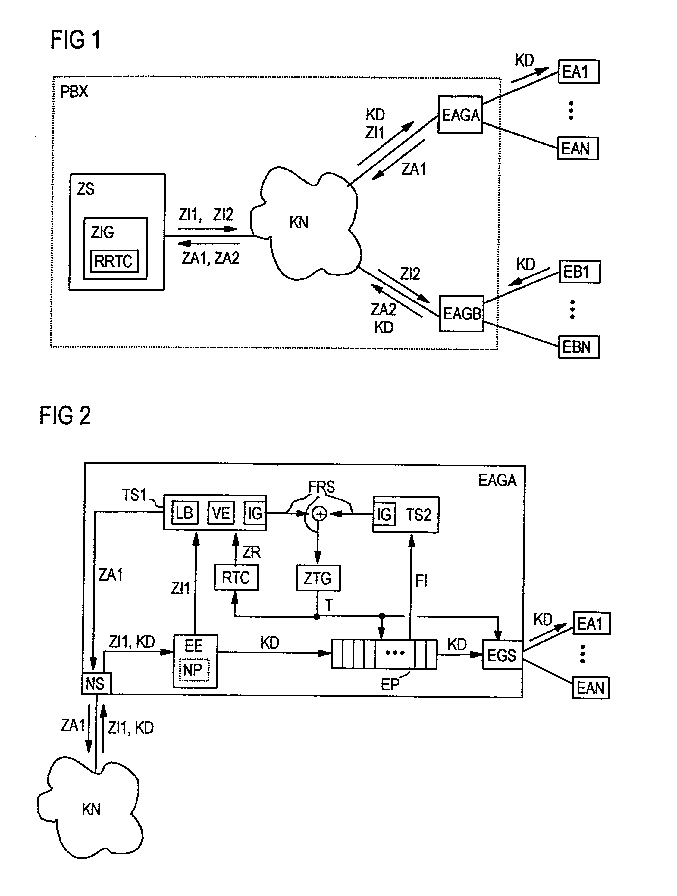
[0006]A communications system component is synchronized by readjusting the clock frequency of a clock generator intended to prescribe the transmission data rate for communications data whose transmission involves the communications system component in question. In this case, the clock frequency is readjusted by comparing received time information with a current time value on a real time clock whose timing is controlled, in accordance with the present invention, by a timing pulse from the clock generator actually provided for prescribing the transmission data rate for communications data which are to be transmitted. The readjustment of the clock generator's clock frequency is thus indirectly used to adjust the real time clock itself on the basis of the time information received. This indirect adjustment prevents abrupt changes in the time indicated by the real time clock and attenuates effects of delay time fluctuations in received time information.
[0008]In accordance with one advantageous embodiment of the present invention, the clock generator in a communications system component can be temperature stabilized or temperature compensated. To increase the clock accuracy, the clock generator also can be produced on the basis of the “2-oscillator concept”. In this context, a main oscillator and a temperature stabilized or temperature compensated reference oscillator which regulates the clock frequency of the main oscillator and otherwise freewheels is provided. The more accurate the clock generator in a communications system component, the longer the time intervals for which the communications system component in question remains in sync even without receiving time information.
[0009]In accordance with another advantageous embodiment of the present invention, a communications system component can be sent the time information wirelessly; e.g., from a GPS satellite (global positioning system), from a time signal transmitter, such as DCF77, or from a time information transmitter associated with the communications system. For this purpose, the time information reception device in the communications system component in question has a radio reception device for wirelessly receiving the time information. Due to the very short delay time for time information transmitted by radio, this allows very accurate synchronization to be achieved.
[0010]Alternatively, a communications system component also can be sent time information via the communications network from a time information transmitter, such as in the form of a time information server, which is likewise coupled to the communications network. As such, an existing network infrastructure also can be used for synchronizing the communications system components. This alternative allows a complex radio reception device to be dispensed with in the communications system components which are to be synchronized. Instead, time information easily can be received by coupling the time information reception device in a communications system component to the communications network via a network interface and providing it with the ability to extract time information from a data stream transmitted via the communications network.
[0012]To improve the accuracy of synchronization, a communications system component can have a timing device for measuring the time difference between a request for and reception of time information, and a delay time determination device for ascertaining an estimate of the delay time for the time information from the time information transmitter to the communications system component on the basis of the measured time difference. Assuming that the delay time for the request approximately matches the delay time for the time information, the delay time for the time information is then found to be half the measured time difference. The accuracy of the estimate of the delay time for time information can be increased by determining the estimate from a mean value for time differences measured for a number of requests, or variables derived from the time differences. This makes it possible to compensate for delay time fluctuations for the data transmitted via the communications network. Accordingly, the comparison device in the communications system component can be designed such that the ascertained estimate of the delay time for the time information is taken into account in the comparison result; e.g., by correcting the time information or the time value indicated by the real time clock.
[0016]For the purposes of clock frequency regulation, a data stream of communications data received via the communications network, such as voice data, preferably can be used. Since communications data, particularly voice data, are frequently transmitted at a precisely maintained transmission rate oriented to the timing of the transmitter for the communications data when a connection has been set up, the clock frequency of the clock generator can be stabilized fairly precisely using received communications or voice data.

Problems solved by technology

As such, relatively complex communications network structures can be produced only with a great deal of effort, however.

Method used


Image

  • System for synchronizing communications system components coupled via a communications network
  • System for synchronizing communications system components coupled via a communications network

Examples


Embodiment Construction

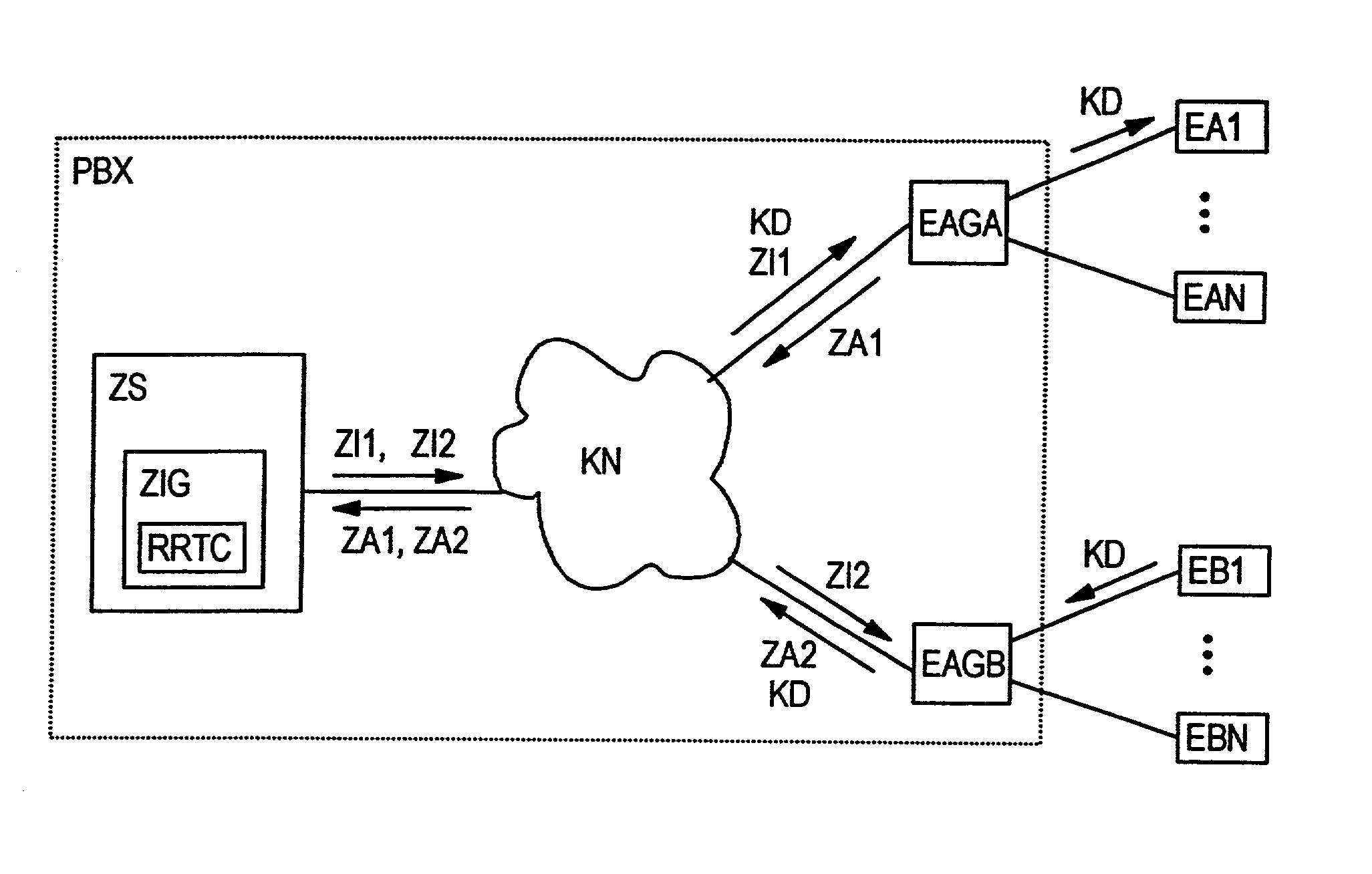
[0021]FIG. 1 shows, schematically, a communications system with an exchange PBX distributed over a communications network KN and terminals EA1, . . . , EAN, and EB1, . . . , EBN connected to the exchange. In this arrangement, the exchange PBX has a central controller ZS and terminal connection groups EAGA and EAGB as communications system components coupled via the communications network KN. The terminal connection groups belong to the “peripheral section” of the exchange PBX. The terminal connection group EAGA couples the terminals EA1, . . . , EAN to the exchange PBX, and the terminal connection group EAGB couples the terminals EB1, . . . , EBN to the exchange PBX. The central controller ZS, for its part, has a time information transmitter ZIG having a reference real time clock RRTC. The reference real time clock RRTC can be adjusted on the basis of world time information received from a satellite; for example, using a GPS (global positioning system) receiver.

[0022]The communicati...


PUM


Abstract

To synchronize communications system components coupled via a communications network, a time information transmitter is provided which is used to transmit time information, possibly on request, relating to the communications system components. The communications system components each have a clock generator, which needs to be synchronized, and a real time clock, where the clock generator both determines the transmission rate for communications data which are to be transmitted and prescribes the time base for the real time clock. In addition, the communications system components each have a comparison device for comparing received time information with a current time value indicated by the real time clock, and a clock frequency controller for regulating the clock frequency of the clock generator on the basis of the comparison result.

Description

BACKGROUND OF THE INVENTION[0001]In the course of current development taking place, communications systems and control thereof are becoming increasingly decentralized. In this regard, a communications system is split into individual subsystems coupled via a communications network, such as a local area network (LAN) or a network based on an internet protocol (IP). This allows, by way of example, components of a relatively large exchange to be distributed over a communications network.[0002]Contemporary communications systems normally provide a large number of communications services and service features. For some of these communications services and service features, such as for “CBO services” (continuous bit stream operation), which include fax, modem, voice and video transmissions, it is necessary for the respective communications system components involved to be in sync for communications data which are to be transmitted.[0003]Arrangements for synchronizing communications system c...

Claims


Application Information

Patent Timeline
Patent Type & Authority Patents(United States)
IPC IPC(8): H04J3/06H04J3/24H04L12/56G06F1/14H04L7/00H04L29/06
CPCG06F1/14H04J3/0664H04L69/28H04J3/0682
Inventor HEITMANN, JUERGEN
Owner RINGCENTRAL INC
Learn More