X-ray computed tomography apparatus

Active Publication Date: 2006-08-01
TOSHIBA MEDICAL SYST CORP
View PDF11 Cites 55 Cited by
  • Summary
  • Abstract
  • Description
  • Claims
  • Application Information

AI Technical Summary

Benefits of technology

[0014]It is an object of the present invention to allow an X-ray computed t

Problems solved by technology

If a scan is stopped halfway by the interlock function, the contrast enhancement effect is almost lost.
Since the slice thickness is determined depending on a diaphragm aperture width, it is determined before data acquisition, and there is basically no degree of freedom in changing

Method used


Image

  • X-ray computed tomography apparatus
  • X-ray computed tomography apparatus
  • X-ray computed tomography apparatus

Examples


first embodiment

(First Embodiment)

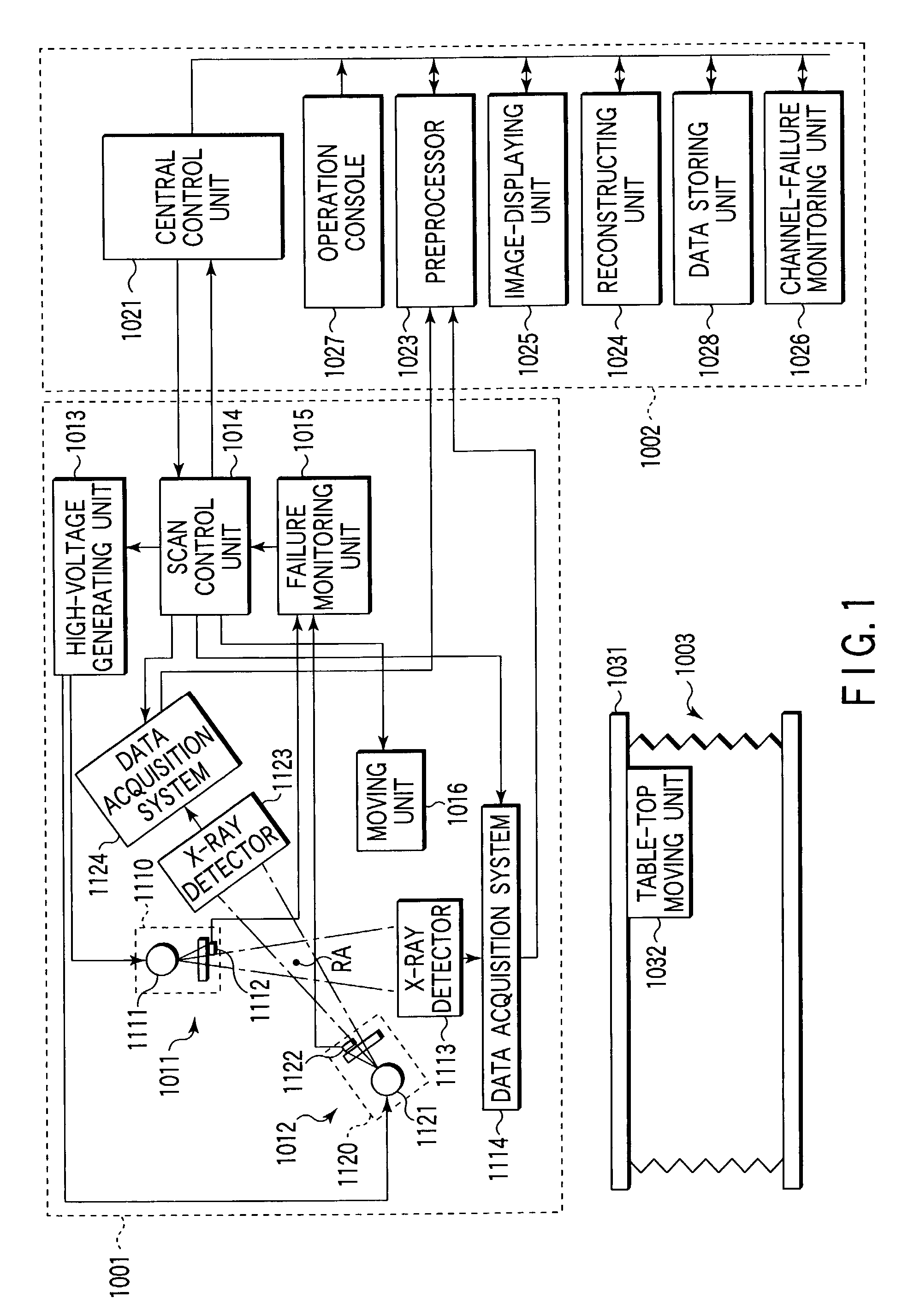
[0070]FIG. 1 shows the arrangement of the main part of an X-ray computed tomography apparatus according to this embodiment. The X-ray computed tomography apparatus according to the embodiment is comprised of a scan gantry 1001, computer device 1002, and bed 1003. The scan gantry 1001 is a constituent element for acquiring projection data about a subject to be examined. This projection data is loaded into the computer device 1002 and subjected to processing such as image reconstruction. The subject is inserted into the imaging area of the scan gantry 1001 while lying on the table-top of the bed. The bed 1003 is equipped with a table-top moving unit 1032 for electrically moving a table-top 1031 along its longitudinal axis (almost equivalent to the body axis of the subject laid on the bed). The computer device 1002 is comprised of a central control unit 1021, a preprocessor 1023 connected to the central control unit 1021 via a data / control bus 1022, an operation conso...

second embodiment

(Second Embodiment)

[0102]FIG. 8 shows the arrangement of the main part of an X-ray computed tomography apparatus according to the second embodiment. The X-ray computed tomography apparatus according to this embodiment is comprised of a scan gantry 2001 and a computer device 2002 (not shown). In the computer device 2002, a preprocessor 2023, a reconstructing unit 2024, an image displaying unit 2025, and an operation console 2026 are connected to a central control unit 2021 via a data / control bus 2022.

[0103]The scan gantry 2001 is of a multi-tube type, i.e., has a plurality of data detecting systems, each including an X-ray tube assembly and X-ray detector. In this case, the scan gantry 2001 will be described as a two-tube type gantry. A first data detecting system 2011 is comprised of a first X-ray tube assembly 2110 and first X-ray detector 2113. The first X-ray tube assembly 2110 is mounted together with the first X-ray detector 2113 on a rotating gantry which rotates about a rotat...

third embodiment

(Third Embodiment)

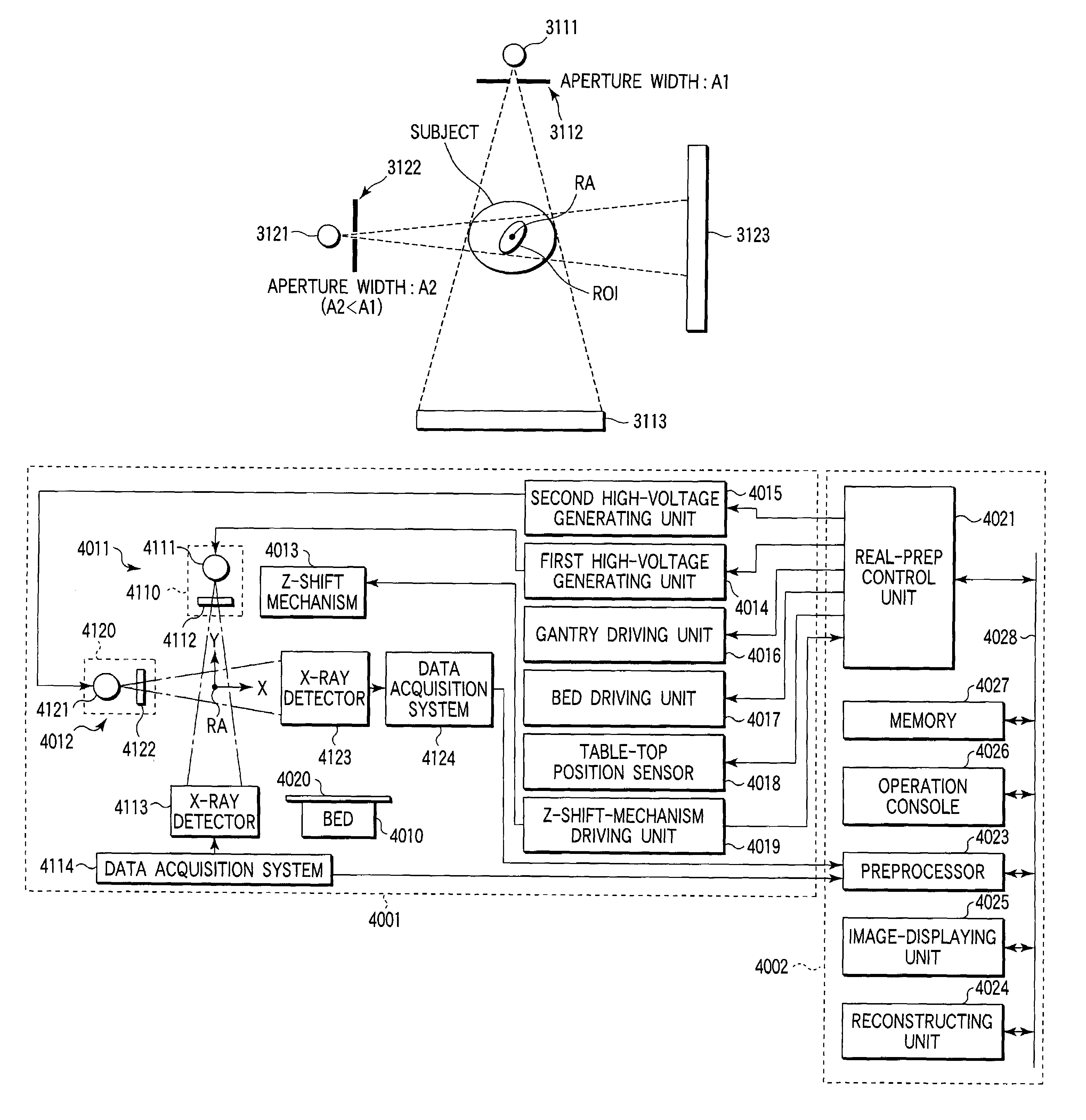
[0125]FIG. 18 shows the arrangement of the main part of an X-ray computed tomography apparatus according to this embodiment. The X-ray computed tomography apparatus according to this embodiment is comprised of a scan gantry 3001, a computer device 3002, and a bed (not shown). The scan gantry 3001 is a constituent element for acquiring projection data about a subject to be examined. This projection data is loaded into the computer device 3002 and subjected to processing such as image reconstruction. The subject is inserted into the imaging area of the scan gantry 3001 while lying on the table-top of the bed.

[0126]The computer device 3002 is comprised of a central control unit 3021 and the following units connected thereto via a data / control bus 3022: a data complementing unit 3023, image reconstructing unit 3024, and image display unit 3025.

[0127]The scan gantry 3001 of a multi-tube type, i.e., has a plurality of data detecting systems, each including an X-ray tube ...


PUM


Abstract

An X-ray computed tomography apparatus of this invention includes a first data detecting system which includes a first X-ray tube and a first X-ray detector and a second data detecting system which includes a second X-ray tube and a second X-ray detector. A reconstructing unit reconstructs image data on the basis of the data detected by at least one of the first and second data detecting systems. A monitoring unit monitors the first data detecting system. In a period during which the first data detecting system is normal, data acquisition is performed by both the first and second data detecting systems. In a period during which the first data detecting system is faulty, data acquisition is performed by the second data detecting system alone.

Description

CROSS-REFERENCE TO RELATED APPLICATIONS[0001]This application is based upon and claims the benefit of priority from the prior Japanese Patent Applications No. 2001-320925, filed Oct. 18, 2001; No. 2001-320926, filed Oct. 18, 2001; No. 2001-320928, filed Oct. 18, 2001; No. 2001-320929, filed Oct. 18, 2001, the entire contents of all of which are incorporated herein by reference.BACKGROUND OF THE INVENTION[0002]1. Field of the Invention[0003]The present invention relates to an X-ray computed tomography apparatus having the function of monitoring abnormal operation such as abnormal discharge or the like in an X-ray tube unit.[0004]2. Description of the Related Art[0005]As is known, a helical scan by which projection data in a wide region of a subject to be examined can be continuously and seamlessly acquired at a high speed is realized by synchronous motions, i.e., the continuous rotation of an X-ray tube, a multi-channel type X-ray detector, and the like and the movement of the table-...

Claims


Application Information

Patent Timeline
IPC IPC(8): A61B6/00G01N23/00G21K1/12H05G1/60A61B6/03
CPCA61B6/032A61B6/4014A61B6/586A61B6/027A61B6/4488
Inventor SHINNO, TOSHIYUKIYANAGIDA, YUJINAKASHIMA, SHIGEYUKIYAOI, YOSHIAKIOKUMURA, MIWAHORINOUCHI, MINORUYAMAZAKI, MASAHIKOISO, MACHIKONAKANISHI, SATORU
Owner TOSHIBA MEDICAL SYST CORP
Why Eureka
Try Eureka