Method and apparatus for measuring and improving efficiency in refrigeration systems

a refrigeration system and efficiency technology, applied in the field of refrigeration system maintenance and tuning, can solve the problems that complex control systems may be required for complex interactions between variables or complex sets of time-constants, and achieve the effect of reducing the topological or computational complexity of the neural network and reducing nois

Inactive Publication Date: 2006-08-08
HUDSON TECHNOLOGIES
View PDF86 Cites 34 Cited by
  • Summary
  • Abstract
  • Description
  • Claims
  • Application Information

AI Technical Summary

Benefits of technology

[0038]In the EXACT method, the value of the parameter change limit, which may be supplied as a predetermined constant or entered by a user, defines a range within which the parameter values of the controller are considered valid. For example, the EXACT method will not set the proportional gain of a controller to a value that exceeds the upper limit of the range defined by the parameter change limit. By specifying a valid parameter range, the EXACT method prevents the controller from using the extreme parameter values that may be a result of hardware or software errors or deficiencies. However, by constraining the parameters to values that fall within a designated range, the EXACT method prevents the use of parameter values outside the range even when such values would provide improved performance; likewise, this constraint fails to detect erroneous or artifact sensor data within the parameter change limit. Thus, an improvement over this technique provides an intelligent analysis of sensor data to perform an automated fault detection and analysis. Thus, using a model of the system constructed during operation, possibly along with manual input of probable normal operational limits, the system may analyze sensor data to determine a probability of system malfunction. If the probability exceeds a threshold, an error may be indicated or other remedial action taken.
[0088]Thus, the present invention does not presume an optimum level of a particular process variable parameter. Rather, a method according to the invention explores the optimum value, and thereafter allows the system to be set near the optimum. Likewise, the method permits periodic “tune-ups” of the system, rather than requiring continuous tight maintenance of a control parameter, although the invention also provides a system and method for achieving continuous monitoring and / or control.

Problems solved by technology

In the case of multivariate analysis and control, interaction between variables or complex sets of time-constants may require a complex control system.
Often, controls often account for time delays inherent in the system, for example to avoid undesirable oscillation or instability.

Method used


Image

  • Method and apparatus for measuring and improving efficiency in refrigeration systems
  • Method and apparatus for measuring and improving efficiency in refrigeration systems
  • Method and apparatus for measuring and improving efficiency in refrigeration systems

Examples


example 1

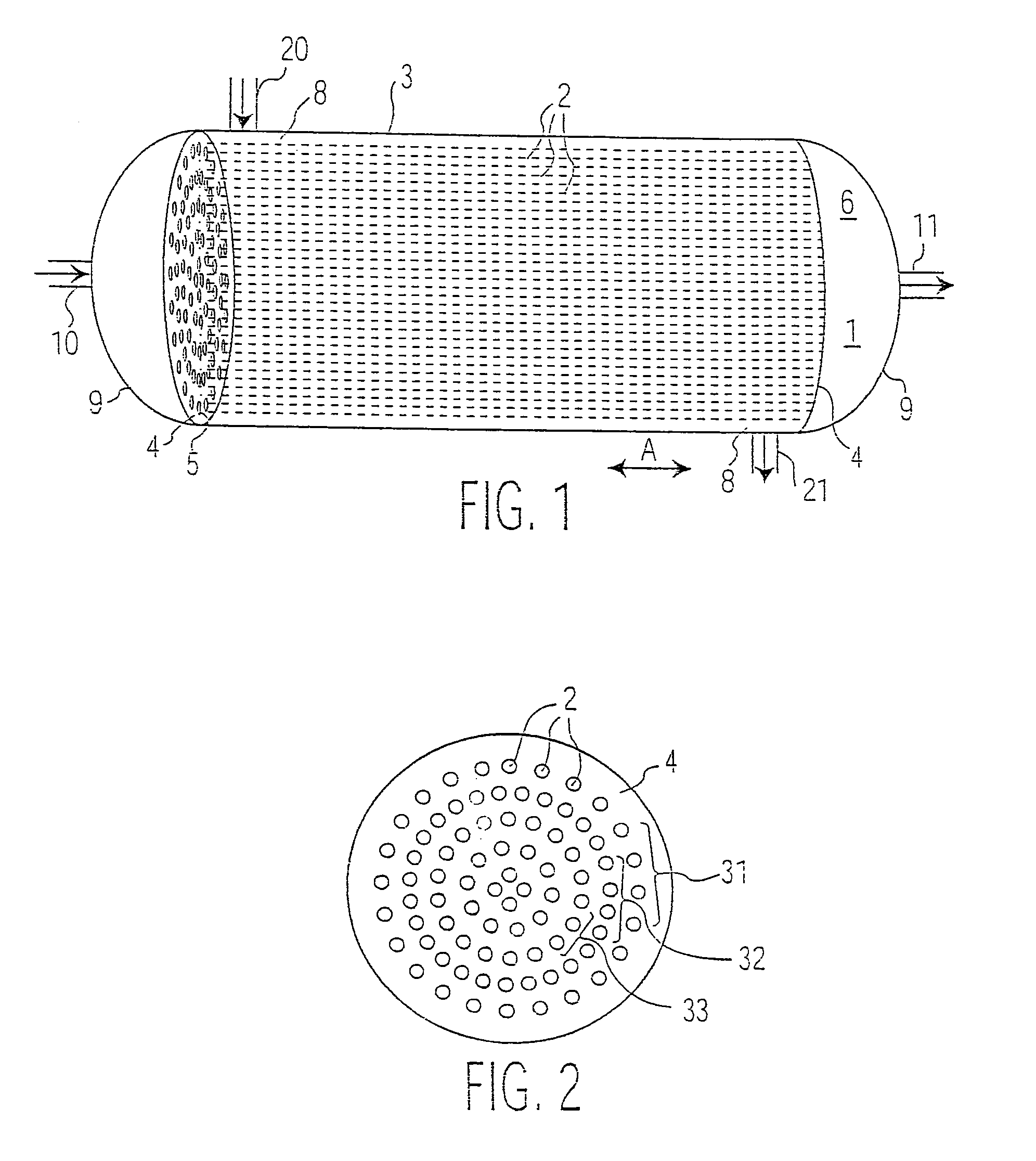
[0099]As shown in FIGS. 1–2, a typical tube in shell heat exchanger 1 consists of a set of parallel tubes 2 extending through a generally cylindrical shell 3′. The tubes 2 are held in position with a tube plate 4, one of which is provided at each end 5 of the tubes 2. The tube plate 4 separates a first space 6, continuous with the interior of the tubes 7, from a second space 8, continuous with the exterior of the tubes 2. Typically, a domed flow distributor 9 is provided at each end of the shell 3, beyond the tube sheet 4, for distributing flow of the first medium from a conduit 10 through the tubes 2, and thence back to a conduit 11. In the case of volatile refrigerant, the system need not be symmetric, as the flow volumes and rates will differ at each side of the system. Not shown are optional baffles or other means for ensuring optimized flow distribution patterns in the heat exchange tubes.

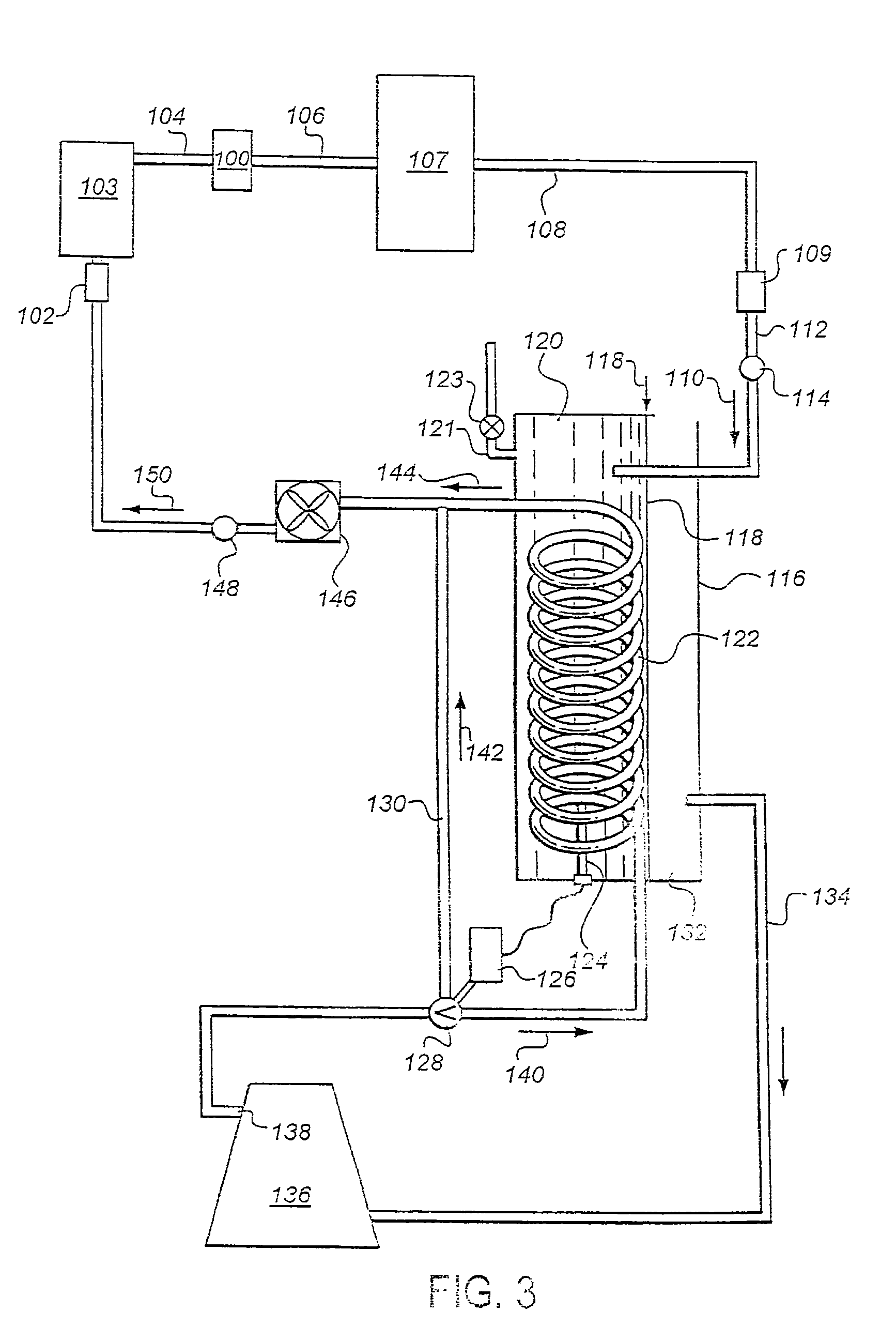
[0100]As shown in FIG. 3, a refrigerant cleansing system provides an inlet 112 for receivi...

example 2

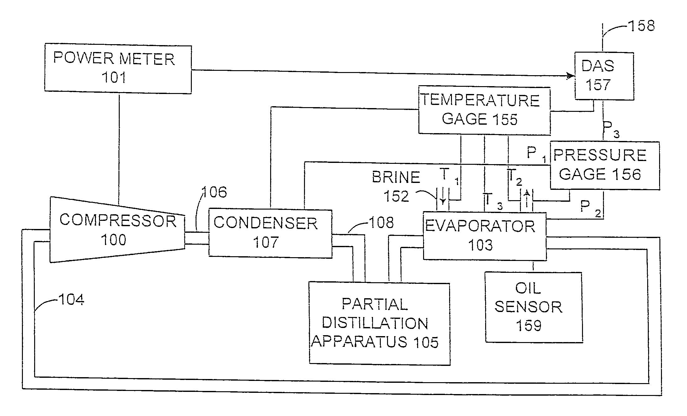
[0107]FIG. 7A shows a block diagram of a first embodiment of a control system according to the present invention. In this system, refrigerant charge is controlled using an adaptive control 200, with the control receiving refrigerant charge level 216 (from a level transmitter, e.g. Henry Valve Co. Melrose Park Ill. LCA series Liquid Level Column with E-9400 series Liquid Level Switches, digital output, or K-Tek Magnetostrictive Level Transmitters AT200 or AT600, analog output), optionally system power consumption (k Watt-hours), as well as thermodynamic parameters, including condenser and evaporator water temperature in and out, condenser and evaporator water flow rates and pressure, in and out, compressor RPM, suction and discharge pressure and temperature, and ambient pressure and temperature, all through a data acquisition system for sensor inputs 201. These variables are fed into the adaptive control 200 employing, nonlinear model of the system, based on neural network 203 techno...

example 3

[0109]A second embodiment of the control system employs feedfoward optimization control strategies, as shown in FIG. 7B. FIG. 7B shows a signal-flow block diagram of a computer-based feedforward optimizing control system. Process variables 220 are measured, checked for reliability, filtered, averaged, and stored in the computer database 222. A regulatory system 223 is provided as a front line control to keep the process variables 220 at a prescribed and desired slate of values. The conditioned set of measured variables are compared in the regulatory, system 223 with the desired set points from operator 224A and optimization routine 224B. Errors detected are then used to generate control actions that are then transmitted as outputs 225 to final control elements in the process 221. Set points for the regulatory system 223 are derived either from operator input 224A or from outputs of the optimization routine 224B. Note that the optimizer 226 operates directly upon the model 227 in arr...


PUM

PropertyMeasurementUnit
temperatureaaaaaaaaaa
energy costaaaaaaaaaa

Abstract

An apparatus for optimizing an efficiency of a refrigeration system, comprising means for measuring a refrigeration efficiency of an operating refrigeration system: means for altering a process variable of the refrigeration system during efficiency measurement: and a processor for calculating a process variable level which achieves an optimum efficiency. The process variables may include refrigerant charge and refrigerant oil concentration in evaporator.

Description

[0001]The present application is a continuation of U.S. patent application Ser. No. 10 / 338,941, filed Jan. 8, 2003 (allowed), which is a continuation-in-part of U.S. patent application Ser. No. 09 / 577,703 filed May 23, 2000, now U.S. Pat. No. 6,505,475, which claims benefit of priority from U.S. Provisional Patent Application 60 / 150,152 filed Aug. 20, 1999, and U.S. Provisional Patent Application 60 / 174,993 filed Jan. 7, 2000, each of which is expressly incorporated herein by reference in its entirety.FIELD OF THE INVENTION[0002]The present invention relates to the fields of repair, maintenance and tuning of refrigeration systems, and more particularly for systems and methods for measuring, analyzing and improving the efficiency of refrigeration systems.BACKGROUND OF THE INVENTION[0003]In the field of refrigeration and chillers, the evaporator heat exchanger is a large structure, containing a plurality of parallel tubes, within a larger vessel comprising a shell, through which refri...

Claims


Application Information

Patent Timeline
Patent Type & Authority Patents(United States)
IPC IPC(8): C09K5/04F25B1/00F25B31/00G01K13/00F25B49/02
CPCF25B49/02F25B31/004F25B2500/18F24F11/30F24F11/32F24F11/46F24F11/62F24F2110/00F24F2130/40F24F2140/60F25B6/04F25B39/02F25B43/02F25B45/00F25B2339/0242F25B2500/05F25B2500/19F25B2600/2523F25B2700/03F25B2700/151F25B2700/195F25B2700/197F25B2700/2116F25B2700/2117F25B2700/21171G05B13/041
Inventor ZUGIBE, KEVINSCHMIDT, DOUGLAS
Owner HUDSON TECHNOLOGIES
Why Eureka
Try Eureka