
Lance system for inter-tube inspecting and lancing as well as barrel spraying of heat transfer tubes of steam generator in nuclear power plant

a technology of intertube inspection and lancing, which is applied in the direction of lighting and heating apparatus, applications, tableware, etc., can solve the problems of shortening the overall life of the steam generator, heat stress, and inability to effectively remove sludge deposits from the steam generator, so as to achieve the effect of easy backward movemen

Active Publication Date: 2006-08-08
KOREA HYDRO & NUCLEAR POWER CO LTD
View PDF6 Cites 19 Cited by
  • Summary
  • Abstract
  • Description
  • Claims
  • Application Information

AI Technical Summary

Benefits of technology

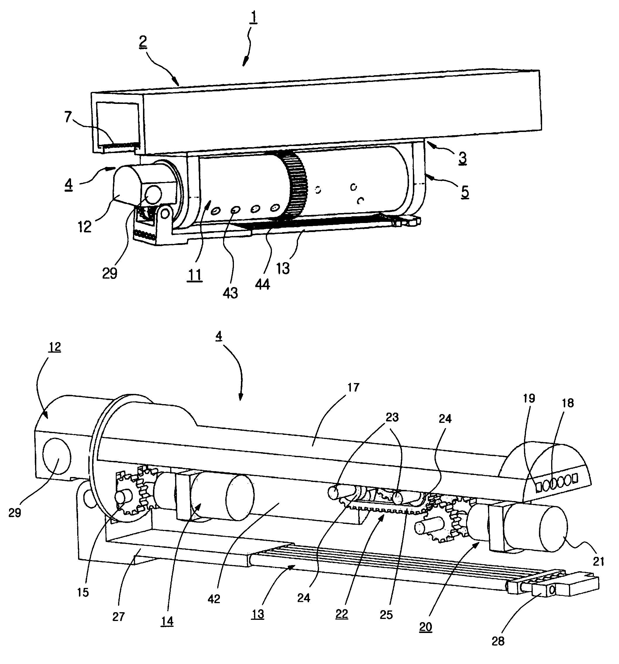
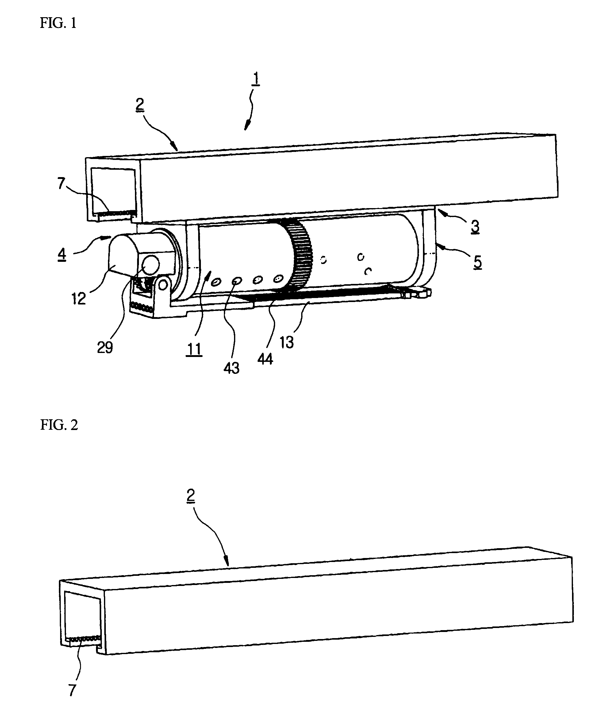
The present invention provides a lance system for inspecting and lancing a steam generator in a nuclear power plant. The system includes a rigid guide support rail, a locomotion box, and a lance body with a circular barrel and a multistage circular pole assembly. The system can approach inner parts of the heat transfer tubes in the steam generator and spray high-pressure water thereto, as well as inspect and lancing them. The system is easy to move back and forth and can reach targeted sludge deposits in the steam generator. The invention solves the problem of foreign substances piled up around heat transfer tubes in the steam generator and ensures the efficient removal of them.

Problems solved by technology

Sludge is piled up in the steam generator, as operating time goes by, deteriorates heat efficiency of the heat transfer tubes in the steam generator, and damages the heat transfer tubes, thereby shortening the overall life span of the steam generator.
The above sludge mainly contains oxidized steel and oxidized copper, and is cohered, in case that the sludge is not removed from the steam generator, and is then stuck between the heat transfer tubes, thereby causing heat stress.
However, using these equipment and procedures, it is impossible to effectively remove sludge deposits from the steam generator.
However, in the above conventional lance systems, there exists a high possibility that the nozzle head experiences excessive vibration, when the nozzle head moves to the inner part of the steam generator, caused by an imbalance of the repulsive forces of the high-pressure water ejected from both directions during lancing, thereby being capable of seriously damaging the surfaces of the heat transfer tubes.
In case that the two arrays of nozzles attached to the nozzle head are arranged apart at an angle less than 180 degrees, strong repulsive force is imposed on the end of the circular rod, thus causing permanent deformation of the circular rod.
The former had several technical problems, and the latter employed flexible means which could be bent by an angle of 90 degrees along the BDL so that the lance system could approach the inner parts of the heat transfer tubes.

Method used


Image

  • Lance system for inter-tube inspecting and lancing as well as barrel spraying of heat transfer tubes of steam generator in nuclear power plant
  • Lance system for inter-tube inspecting and lancing as well as barrel spraying of heat transfer tubes of steam generator in nuclear power plant
  • Lance system for inter-tube inspecting and lancing as well as barrel spraying of heat transfer tubes of steam generator in nuclear power plant

Examples


Embodiment Construction

[0036]Now, preferred embodiments of the present invention will be described in detail with reference to the annexed drawings.

[0037]As shown in FIG. 9, a lance system 1 of the present invention serves to inspect or lance sludge piled up around heat transfer tubes 101 of a steam generator 100 provided with a high-temperature water inlet 103 and a low-temperature water outlet 104, and is installed in a nuclear power plant through a handling hole 102.

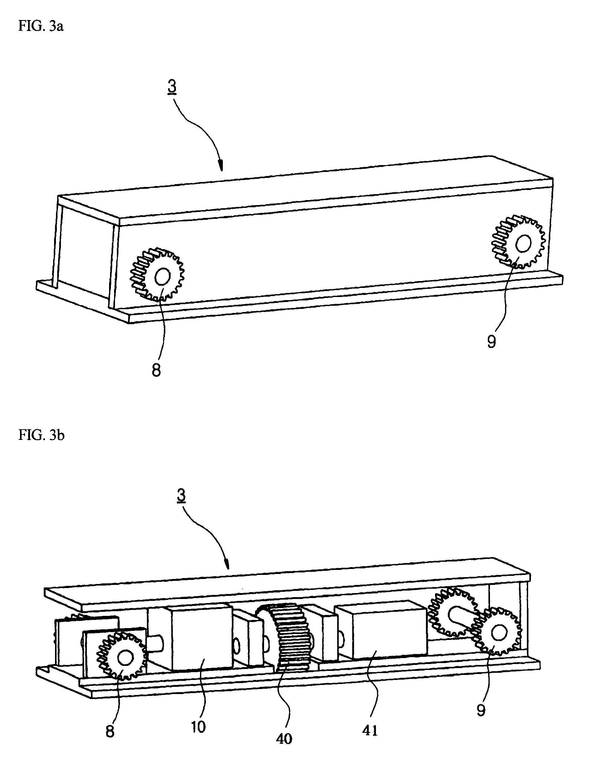
[0038]The lance system 1 of the present invention serves to remove foreign substances piled up around the heat transfer tubes 101 in the steam generator 100 using high-pressure water, and comprises a rigid guide support rail 2, a locomotion box 3, and a lance body 4. The rigid guide support rail 2 is arranged above a BDL (Blow Down Lane) 105 positioned at the center of the steam generator 100. The locomotion box 3 includes a motor drive unit 10 for inducing a rectilinear motion of the lance body 4 along the rigid guide support rail 2, and a...


PUM


Abstract

Disclosed is a lance system for inter-tube inspecting and lancing as well as barrel spraying of heat transfer tubes of a steam generator in a nuclear power plant, so that foreign substances piled up around heat transfer tubes in the steam generator are removed using high-pressure water. The lance system includes a rigid guide support rail positioned above a Blow Down Lane (BDL) at the center of the steam generator, a locomotion box including a motor drive unit for inducing a rectilinear motion of a lance body and a motor drive unit for inducing a rotational motion of the lance body centering on a horizontal axis, the lance body including a circular barrel including a motor drive unit for vertically erecting or horizontally laying down a multistage circular pole assembly, and a flat plate provided with linear passages for passing high-pressure water hoses, an optical cable and control rods therethrough, a circular drum assembly for stably connecting the high-pressure water hoses, the optical cable and the control rods, and the multistage circular pole assembly being extensible and contractible by the movement of the control rods obtained by engaging teeth of a toothed belt unit, driven by a motor and positioned in the circular barrel, with gear teeth of the control rods, and two nozzle blocks, for barrel spraying, provided with barrel spray nozzles fixedly assembled therewith, symmetrically fixed to the inner surface of the circular barrel, wherein the multistage circular pole assembly is vertically erected in the operation of inter-tube lancing and inspecting, in which the lance system approaches inner parts of the heat transfer tubes and sprays the high-pressure water thereto, and is maintained in a horizontally laid-down position in the operation of barrel spraying.

Description

BACKGROUND OF THE INVENTION[0001]1. Field of the Invention[0002]The present invention relates to a lance system, for inter-tube inspecting and lancing as well as barrel spraying of heat transfer tubes of a steam generator in a nuclear power plant, in which foreign substances, such as sludge deposits piled up around heat transfer tubes, are inspected or removed by spraying high-pressure water.[0003]2. Description of the Related Art[0004]As well known to those skilled in the art, a nuclear power plant rotates a turbine by means of the force of steam generated by heating water using heat generated by nuclear fission of uranium, and operates a power generator using the above rotary force, thereby producing electricity. Heat transfer tubes are densely arranged in a steam generator. Since water of a high temperature, which is contaminated with radioactivity, flows inside the heat transfer tubes, and water of a low temperature, which is not contaminated with radioactivity, flows outside th...

Claims


Application Information

Patent Timeline
Patent Type & Authority Patents(United States)
IPC IPC(8): F22B37/48F22B37/54F02D7/00F22B37/00G21F9/00
CPCF22B37/003A47G21/04A47G2400/06A47J43/282
Inventor HWANG, KWON SANGSUNG, HYUNG JINJEONG, WOO TAEHONG, SUNG YULL
Owner KOREA HYDRO & NUCLEAR POWER CO LTD
Learn More