
High repetition rate laser produced plasma EUV light source

a laser and high repetition rate technology, applied in the field of system for the generation of euv light, can solve the problems of reducing the economic efficiency of the light source, high uv radiation from the euv source, and incredibly tight requirements

Active Publication Date: 2006-08-08
ASML NETHERLANDS BV
View PDF57 Cites 141 Cited by
  • Summary
  • Abstract
  • Description
  • Claims
  • Application Information

AI Technical Summary

Problems solved by technology

Many issues of collector efficiency need to be addressed, including debris management, which can interfere with the ability to deliver the required light energy to the intermediate focus and also decrease economic efficiency of the light source if debris, e.g., requires frequent replacement of the collector due to inability to control debris deposition over time.
With a 248 nm drive laser, as opposed to an infrared drive laser, even a small amount of scattered laser light may lead to high levels of UV radiation from the EUV source.
This is an incredibly tight requirement, for both LPPs and DPPs.

Method used


Image

  • High repetition rate laser produced plasma EUV light source
  • High repetition rate laser produced plasma EUV light source
  • High repetition rate laser produced plasma EUV light source

Examples


Embodiment Construction

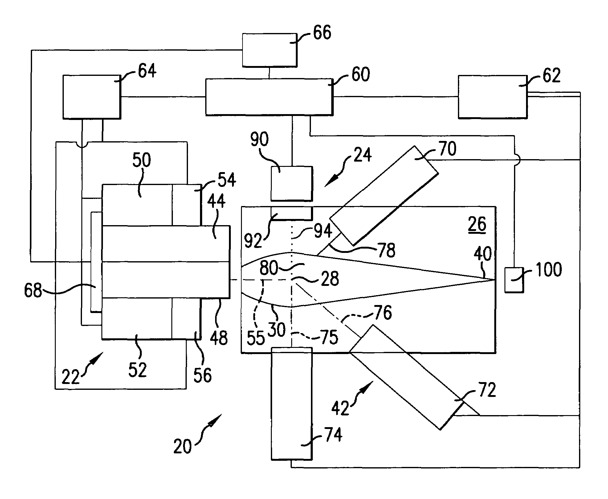
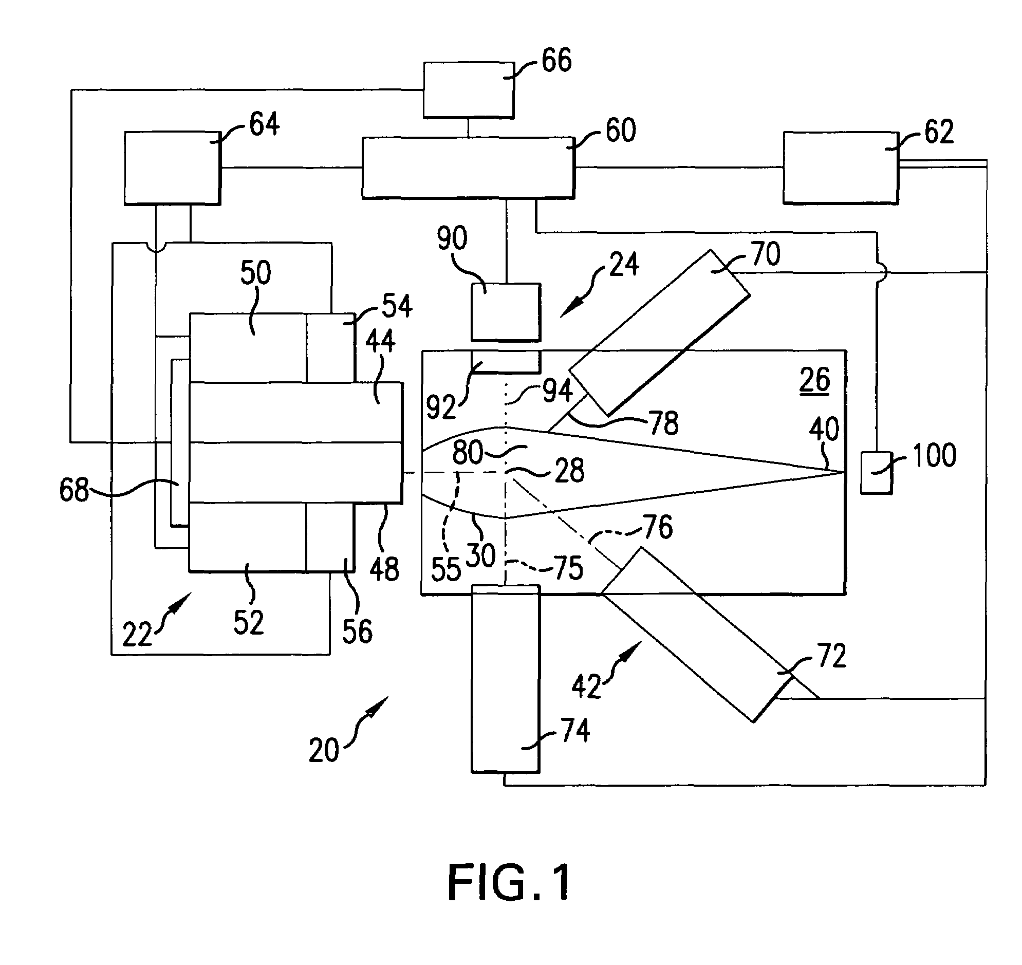
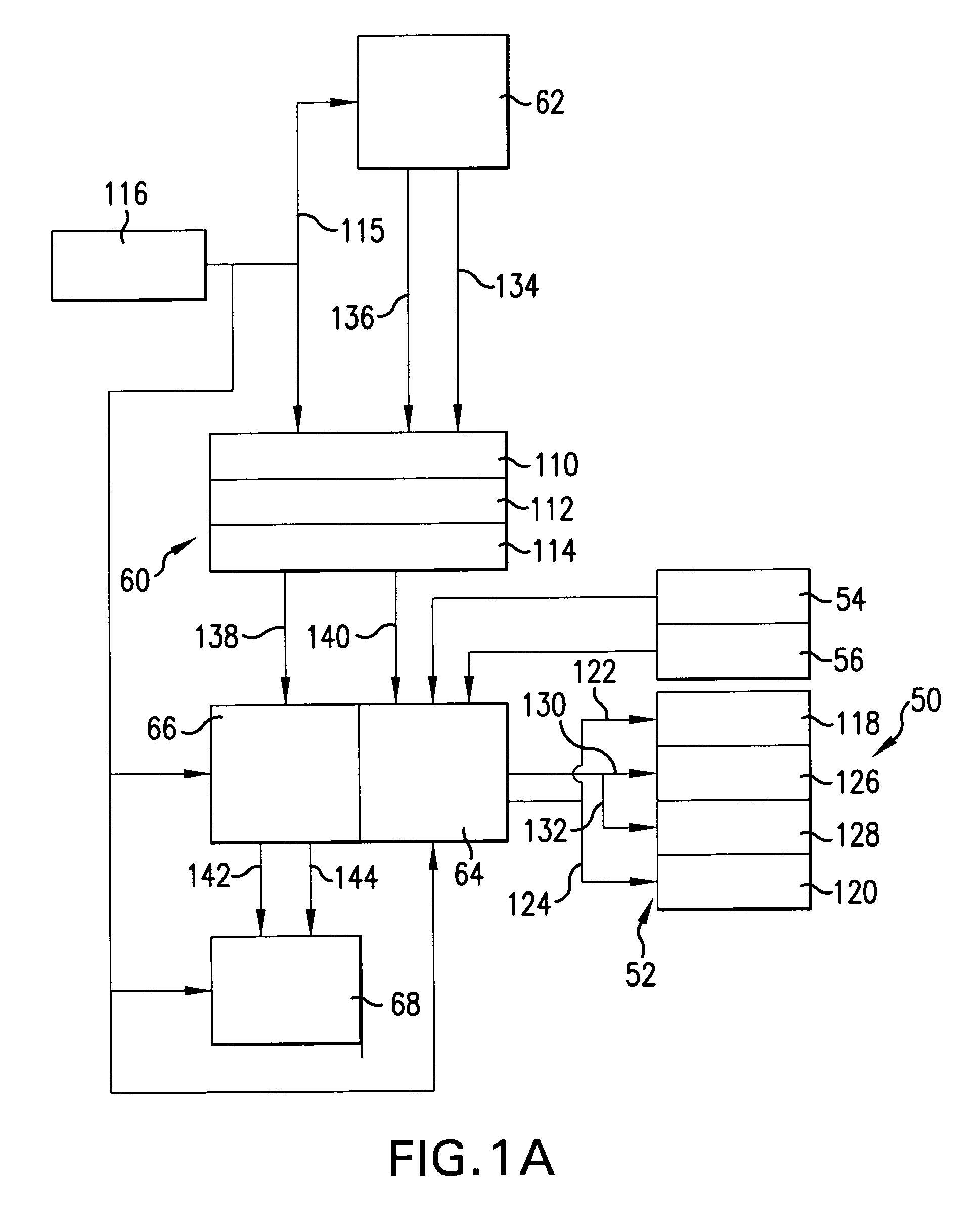
[0025]Turning now to FIG. 1 there is shown a schematic view of an overall broad conception for an EUV light source, e.g., a laser produced plasma EUV light source 20 according to an aspect of the present invention. The light source 20 may contain a pulsed laser system 22, e.g., a gas discharge excimer or molecular fluorine laser operating at high power and high pulse repetition rate and may be a MOPA configured laser system, e.g., as shown in U.S. Pat. Nos. 6,625,191, 6,549,551, and 6,567,450. The light source 20 may also include a target delivery system 24, e.g., delivering targets in the form of liquid droplets, solid particles or solid particles contained within liquid droplets. The targets may be delivered by the target delivery system 24, e.g., into the interior of a chamber 26 to an irradiation site 28, otherwise known as an ignition site or the sight of the fire ball. Embodiments of the target delivery system 24 are described in more detail below.

[0026]Laser pulses delivered ...


PUM

PropertyMeasurementUnit
wavelength rangesaaaaaaaaaa
diameteraaaaaaaaaa
pressureaaaaaaaaaa

Abstract

An EUV light source apparatus and method are disclosed, which may comprise a pulsed laser providing laser pulses at a selected pulse repetition rate focused at a desired target ignition site; a target formation system providing discrete targets at a selected interval coordinated with the laser pulse repetition rate; a target steering system intermediate the target formation system and the desired target ignition site; and a target tracking system providing information about the movement of target between the target formation system and the target steering system, enabling the target steering system to direct the target to the desired target ignition site. The target tracking system may provide information enabling the creation of a laser firing control signal, and may comprise a droplet detector comprising a collimated light source directed to intersect a point on a projected delivery path of the target, having a respective oppositely disposed light detector detecting the passage of the target through the respective point, or a detector comprising a linear array of a plurality of photo-sensitive elements aligned to a coordinate axis, the light from the light source intersecting a projected delivery path of the target, at least one of the which may comprise a plane-intercept detection device. The droplet detectors may comprise a plurality of droplet detectors each operating at a different light frequency, or a camera having a field of view and a two dimensional array of pixels imaging the field of view. The apparatus and method may comprise an electrostatic plasma containment apparatus providing an electric plasma confinement field at or near a target ignition site at the time of ignition, with the target tracking system providing a signal enabling control of the electrostatic plasma containment apparatus. The apparatus and method may comprise a vessel having and intermediate wall with a low pressure trap allowing passage of EUV light and maintaining a differential pressure across the low pressure trap. The apparatus and method may comprise a magnetic plasma confinement mechanism creating a magnetic field in the vicinity of the target ignition site to confine the plasma to the target ignition site, which may be pulsed and may be controlled using outputs from the target tracking system.

Description

FIELD OF THE INVENTION[0001]The present invention relates to a system for the generation of EUV light using a laser produced plasma and discrete targets in the form of solid particles or droplets or solid particles imbedded in a droplet delivered to an irradiating site for irradiation by a pulsed laser beam.RELATED APPLICATIONS[0002]The present application is related to a application Ser. No. 10 / 798,740, COLLECTOR FOR EUV LIGHT SOURCE, filed on Mar. 10, 2004, the disclosure of which is hereby incorporated by reference.BACKGROUND OF THE INVENTION[0003]LPP EUV sources have been under discussion for some time. As the requirements for, e.g., smaller and smaller integrated circuit critical dimension lithography and the concomitant requirement for shorter and shorter wavelength light sources, in the ranges of tens of tens of nanometers (e.g., 10–30), the need for a workable EUV light source that can also meet all of the requirements for power, repetition rate, dose stability, and the like...

Claims


Application Information

Patent Timeline
Patent Type & Authority Patents(United States)
IPC IPC(8): H01J35/20G01J1/00G03F7/20H01J65/04H05G2/00
CPCB82Y10/00H05G2/008H05G2/003G03F7/70033G01J1/00G03F7/20H01J35/20H01J65/04
Inventor AKINS, ROBERT P.SANDSTROM, RICHARD L.PARTLO, WILLIAM N.FOMENKOV, IGOR V.ALGOTS, JOHN MARTINJACQUES, ROBERT N.PALENSCHAT, FREDERICKSONG, JUN
Owner ASML NETHERLANDS BV
Learn More