Green welding laser

a green welding laser and generator technology, applied in the direction of optical resonator shape and construction, instruments, manufacturing tools, etc., can solve the problems of inefficiency, insufficient yag lasers that are often used for low power (500 w (watts)), and insufficient yag lasers that are often used for welding applications. , to achieve the effect of reducing the number of yag lasers, and reducing the number of y

Inactive Publication Date: 2006-08-08
MIYACHI TECHNOS CORP 1 2 INTEREST
View PDF30 Cites 8 Cited by
  • Summary
  • Abstract
  • Description
  • Claims
  • Application Information

AI Technical Summary

Problems solved by technology

However, light from a CO2 laser may not couple with or be efficiently absorbed by certain metals and alloys.
Similarly, YAG lasers that are often used for low power (<500 W (watts)) welding applications may not couple well or be efficiently absorbed by metals such as copper, gold, aluminum, etc. at room temperature.
However, before reaching the melting temperature the use of a high energy pulse may result in considerable inefficiency in that a significant portion of the laser beam may not be absorbed during the onset of the pulse.
In addition, once the laser pulse couples with the material, the high peak power may add too much energy and cause the material to splash (radiate drops of molten metal) or cause unwanted vaporization of the metal and alloy components.
The undesirable inefficiency and splashing may lead to inconsistent weld results.

Method used


Image

  • Green welding laser
  • Green welding laser
  • Green welding laser

Examples


Embodiment Construction

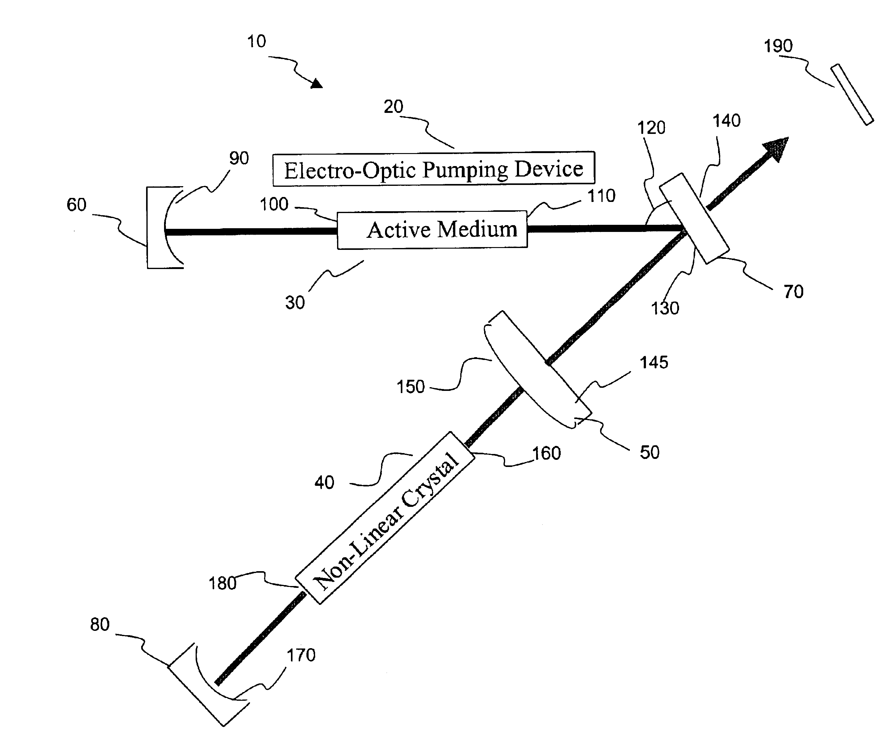
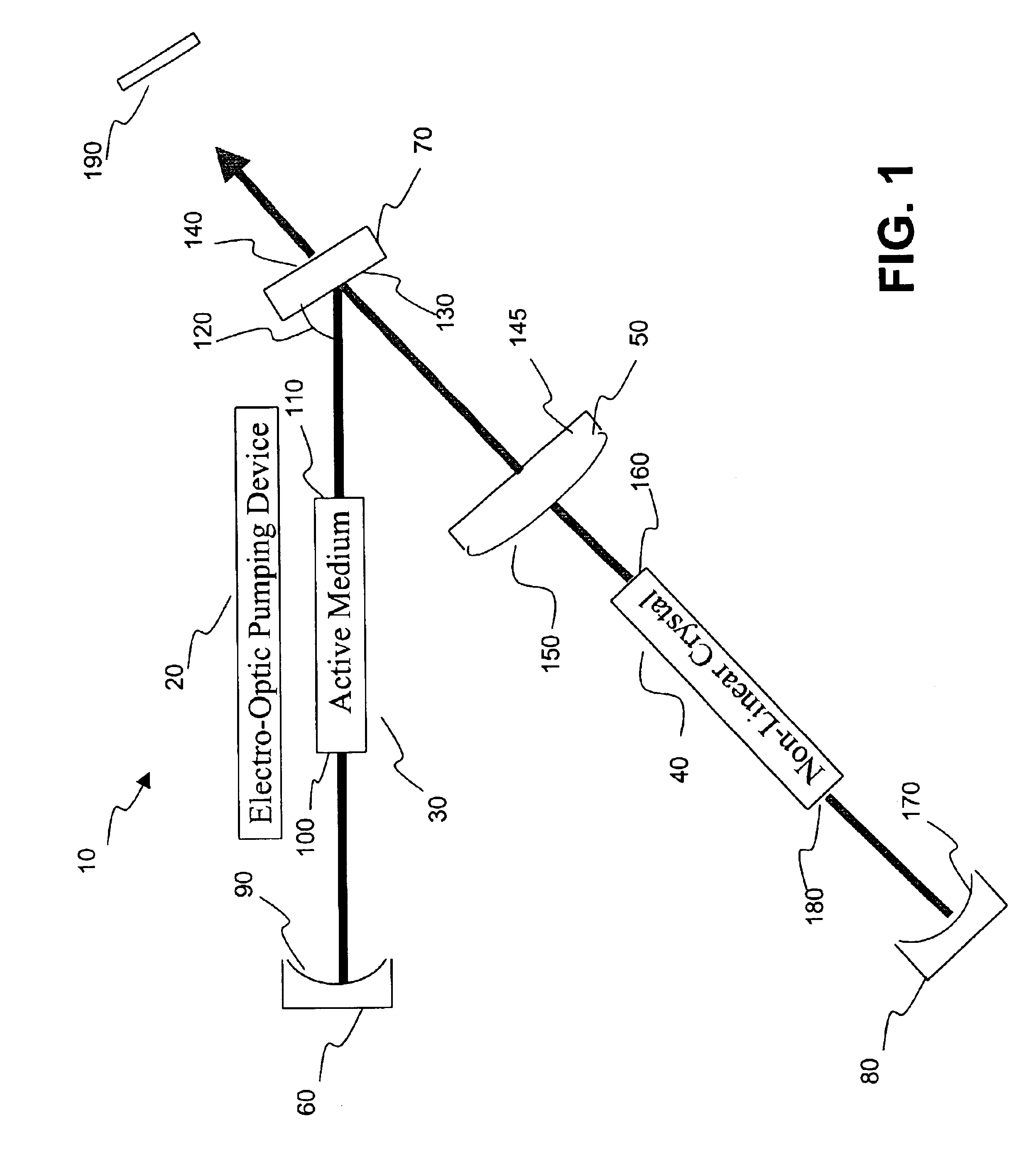
[0011]An exemplary embodiment of the present invention provides a method and apparatus for generating an Nth harmonic frequency beam (N≧2). In accordance with an exemplary embodiment, the harmonic, optical generator may comprise an electro-optic pumping device (e.g., laser diode, flash lamp, etc.) that produces an output pumping radiation which is optically coupled into an active medium disposed within an optical resonator to pump the active medium and to excite the optical resonator at a fundamental wavelength. In the described exemplary embodiment a non-linear electro-optic medium may be coupled to the excited, fundamental optical mode of the optical resonator to produce a non-linear interaction with the fundamental wavelength producing harmonic wavelength photons. The advantages of the present invention may be best understood in the context of an exemplary application, such as, for example, a laser welding system.

[0012]FIG. 1 is a simplified schematic diagram of an exemplary opti...


PUM

PropertyMeasurementUnit
peak poweraaaaaaaaaa
focal lengthaaaaaaaaaa

Abstract

A harmonic system for use with metals and alloys such as titanium, steel, copper, gold, aluminum, etc. is disclosed. The harmonic laser system includes an oscillator cavity having a first end mirror and a harmonic separator mirror, an active medium positioned in the oscillator cavity, an electro-optic pump device for optically pumping the active medium to produce a first optical beam at a fundamental wavelength and a non-linear optical crystal positioned in the oscillator cavity to generate a second optical beam at a harmonic wavelength of the first optical beam, wherein the harmonic separator mirror outputs the second optical beam and reflects the first optical beam.

Description

FIELD OF THE INVENTION[0001]The present invention generally relates to optical harmonic generators and, more particularly relates to an optical harmonic generator for generating a laser output beam for use in a laser spot or seam welding system.BACKGROUND[0002]Recently, lasers have been used in industrial production, particularly for welding, cutting, and surface treatment. In practice laser welding technology is increasingly gaining importance because of the high precision and processing speeds that can be achieved, the low thermal stress on the workpiece, and the high degree of automation which is possible. Current laser welding systems often use a CO2 (carbon dioxide) laser which produces a light beam having a wavelength of 10.6 μm (micro meters), or a solid-state device such as the Nd:YAG laser (Neodymium Yttrium Aluminum Garnet) laser, which produces a light beam having a wavelength of approximately 1.064 μm.[0003]However, light from a CO2 laser may not couple with or be effici...

Claims


Application Information

Patent Timeline
Patent Type & Authority Patents(United States)
IPC IPC(8): H01S3/10G02F1/37B23K26/00H01S3/08H01S3/081H01S3/109
CPCH01S3/109H01S3/0815H04M1/82
Inventor NAKAYAMA, SHINICHIKELKAR, GIRISHBATES, GREGORY
Owner MIYACHI TECHNOS CORP 1 2 INTEREST
Why Eureka
Try Eureka