Automatic gain control for digitized RF signal processing

a technology of automatic gain control and digitized rf signal, which is applied in the direction of pulse technique, transmission monitoring, instruments, etc., can solve the problems of increasing the cost and complexity of the system, not optimizing or well-suited to detecting and processing radar signals, and analog-based designs, so as to achieve the effect of reducing performan

Active Publication Date: 2006-08-08
THE UNITED STATES OF AMERICA AS REPRESENTED BY THE SECRETARY OF THE NAVY
View PDF12 Cites 29 Cited by
  • Summary
  • Abstract
  • Description
  • Claims
  • Application Information

AI Technical Summary

Benefits of technology

[0010]A typical radar signal consists of bursts of RF energy referred to as “pulses.” From the perspective of the intercept receiver, these pulses will vary greatly in amplitude with the rotation of the transmitter's antenna. The invention provides an apparatus and method of AGC that allows the intercept system's signal processor to adjust for these change...

Problems solved by technology

The system, however, includes certain analog components, e.g. a logarithmic amplifier/detector and a track/hold device, and has the above-noted disadvantages regarding such analog-based designs.
Although the system utilizes digital instead of analog components, these are selected for implementation in a pers...

Method used


Image

  • Automatic gain control for digitized RF signal processing
  • Automatic gain control for digitized RF signal processing
  • Automatic gain control for digitized RF signal processing

Examples


Embodiment Construction

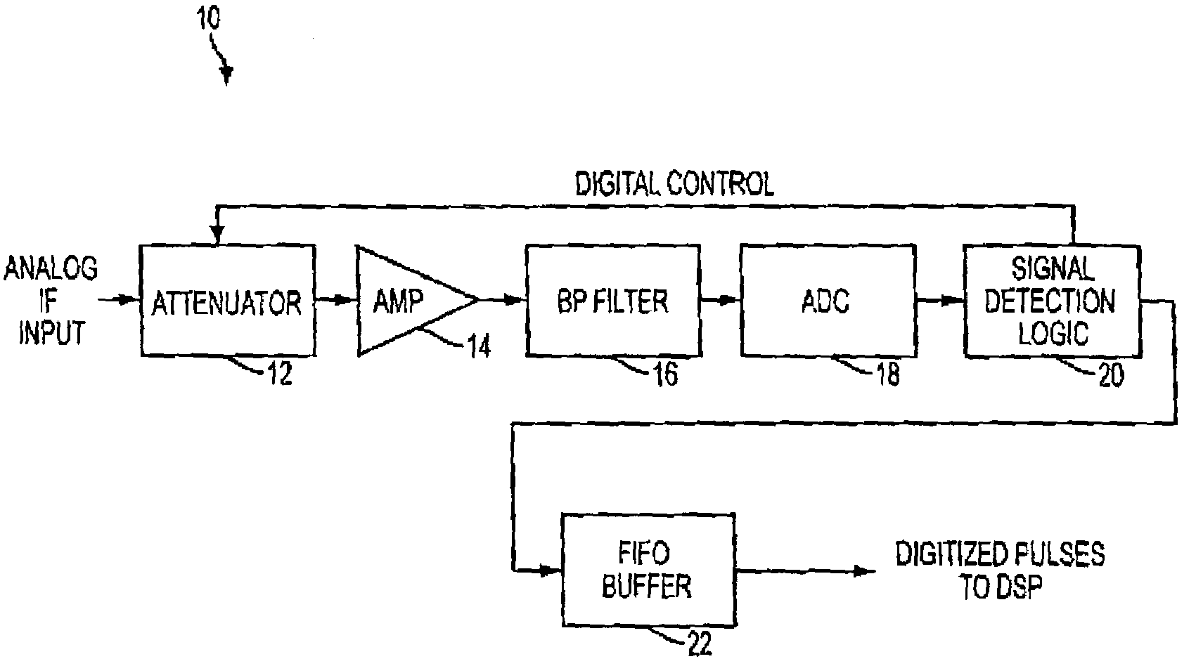
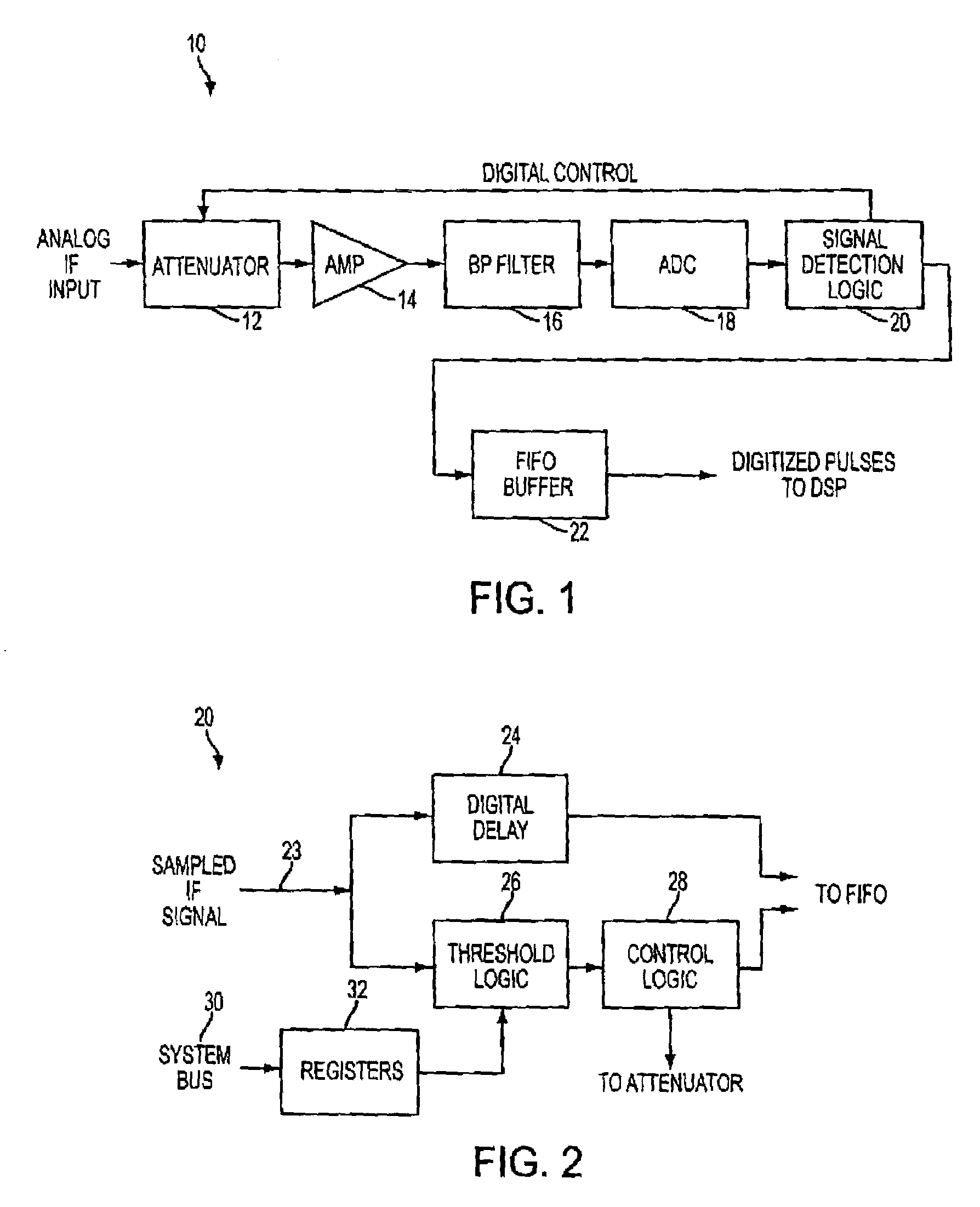
[0017]A digitized AGC signal processor 10 is illustrated in FIG. 1. In this circuit, an analog IF input signal, e.g. of a received radar pulse converted to an IF as described above, is applied to a variable-gain front end that consists of a digitally controlled attenuator 12 with its output applied to a fixed amplifier 14.

[0018]The output of amplifier 14 goes through a bandpass filter 16 which provides anti-aliasing and noise-reduction functions. The filtered signal is applied to an ADC 18 to produce a digitized output signal that is then applied to a signal detection logic circuit 20. As is further discussed below, circuit 10 preferably employs a ¾ Fs bandpass sampling technique. This technique is preferred over the “synchronous downconverter” approach used in previous art techniques because it eliminates the synchronous downconverter hardware, and it requires only one ADC.

[0019]Logic circuit 20 controls the amount of gain setting for attenuator 16 in order to adjust the analog sig...


PUM


Abstract

An automatic gain control RF signal processor for receiver systems, such as radar intercept receivers, includes an attenuator having an input for receiving an analog RF input signal, an amplifier coupled to the attenuator, a bandpass filter coupled to the amplifier output, a single ADC coupled to the bandpass filter, a digital logic circuit, and a FIFO buffer. The digital logic circuit has an input for receiving the ADC output signal, a first output coupled to a variable gain control input of the attenuator, and a second output. The logic circuit includes signal detection logic for detecting the presence of a pulse within the ADC signal, determining a peak amplitude value of the pulse, and based on the peak amplitude value generating an attenuation value at the first output that is applied to the variable gain control input of the attenuator. The sampling logic averages a number of ADC data samples to determine a moving average pulse amplitude, and compares this moving average pulse amplitude to a processing threshold value to determine a delta value with which to adjust an attenuation value for the attenuator, and to determine when to terminate a pulse and reset the attenuation value to zero. The averaging is carried out to determine whether an assigned number m of n samples is above the processing threshold value or whether the pulse should be terminated.

Description

TECHNICAL FIELD[0001]This invention relates to a method and device for automatic gain control in an RF signal processing system. More particularly, the invention relates to the detection and digitized processing of intercepted radar signals.BACKGROUND ART[0002]RF signal processors typically require automatic gain control (AGC) in order to detect and process RF signals that may vary over a wide range of signal strength. Radar and communications receiver systems generally include (1) an antenna, either directional or omnidirectional, (2) a superheterodyne receiver for tuning to a specific RF and converting to an intermediate frequency (IF), (3) a processor for detecting IF signals and for extracting information from these, and (4) a graphical user interface.[0003]Regarding (3), the IF signal detecting and processing component, historically the IF signal has been processed by a combination of analog and digital components. However, recent advancements in technology have allowed direct ...

Claims


Application Information

Patent Timeline
IPC IPC(8): H03D3/24H03G3/00H03G3/30
CPCH03G3/3052H03G3/001
Inventor NICHOLS, GREGORY M.
Owner THE UNITED STATES OF AMERICA AS REPRESENTED BY THE SECRETARY OF THE NAVY
Why Eureka
Try Eureka