Auto-disable safety syringe

Inactive Publication Date: 2006-08-15
JIANGXI HONGDA MEDICAL EQUIP GROUP
View PDF2 Cites 11 Cited by
  • Summary
  • Abstract
  • Description
  • Claims
  • Application Information

AI Technical Summary

Benefits of technology

[0023]Therefore, the syringe of the present invention can protect both medical staffs and patients simultaneously, avoid cross contaminations, and pr

Problems solved by technology

However, the auto-disable syringe still tends to prick or scratch the medical staff during its subsequent handling, this may cause a further contamination, so that the conventional disposable syringe could not achieve a “dual protection”, that is, the conventional syringe could not protect both medical staffs and patients simultaneously.
However, the above safety syringe with a manually retractable needle has a problem in connection between the needle seat and the barrel.
The above connection should be firm and could not be too firm, if the connection is too firm, the needle seat may not be pulled inside the barrel after injection and during destruction, if the connection is not sufficient firm, the injectant may be leaked out and the needle may be automatically retracted during in

Method used


Image

  • Auto-disable safety syringe
  • Auto-disable safety syringe
  • Auto-disable safety syringe

Examples


embodiment 1

[0047] Two-part Type Auto-disable Safety Syringe with a Central Needle and a Luer-lock Conical Fitting of a Needle Seat

first embodiment

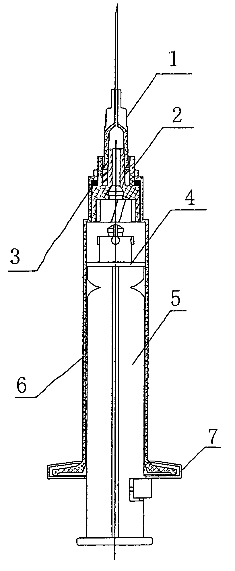
[0048]With reference to FIG. 1 to FIG. 12, FIG. 1 is a schematic structural view of a two-part type auto-disable safety syringe with a central needle and a Luer-lock conical fitting of a needle seat according to the present invention, the auto-disable safety syringe comprises a needle 1, a needle seat 2, a seal 3, a piston 4, a plunger 5, a barrel 6, and plunger positioning plates 7, a finger grip 69 is integrally formed at a rear end (bottom end in FIG. 1 and FIG. 2) of the barrel 6.

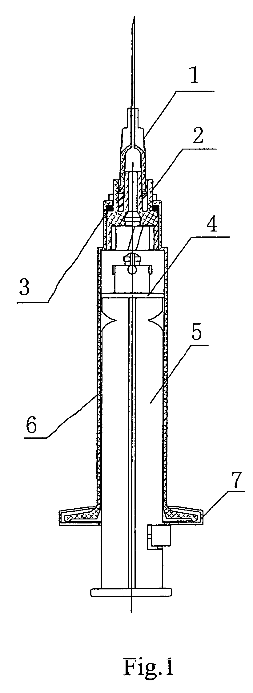
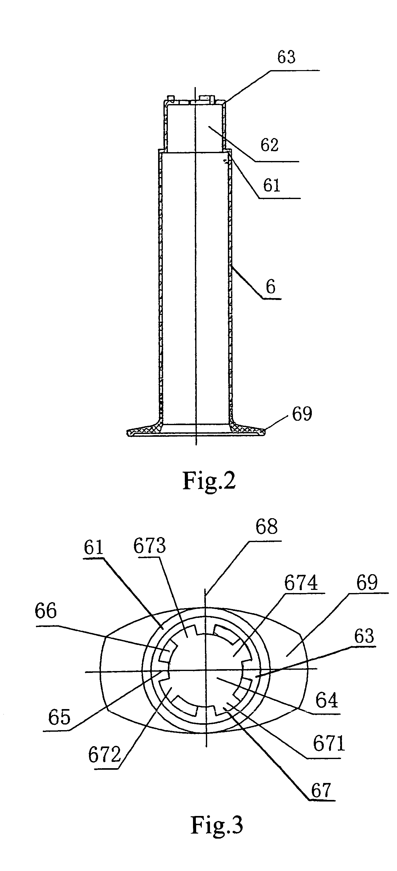
[0049]FIG. 2 is a schematic structural view of the barrel of the auto-disable safety syringe according to the first embodiment of the present invention, and FIG. 3 is a plane view of FIG. 2, a cylindrical needle seat chamber 62 is formed in front of a large top cover 61 provided at a front end (top end in FIG. 2) of the barrel 6, the central line of the needle seat chamber 62 is coincided with that of the barrel 6, that is, the barrel 6 is coaxial with the needle seat chamber 62. A small top cover 63 is...

embodiment 2

[0058] Three-part Type Auto-disable Safety Syringe with an Eccentric Needle and a Luer Conical Fitting of a Needle Seat

[0059]The needle 1, the needle seat 2, the seal 3, the plunger 5, the barrel 6, and the plunger positioning plates 7 in the embodiment 2 are identical with that in the embodiment 1, so that the detail descriptions thereof are omitted here, the embodiment 2 is different from the embodiment 1 in the following.

[0060]In the embodiment 2, as shown in FIG. 13–FIG. 21, the barrel 6 of the syringe has an eccentric head portion, the central line of the needle seat chamber 62 of the barrel 6 is parallel to that of the barrel 6 and positioned on the short axis 68 of the finger grip 69 of the barrel 6.

[0061]The fitting 26 formed at front end of the needle seat 2 is a Luer conical fitting.

[0062]The piston 4 is formed by combination of a piston head 58 with piston rings 59 of the plunger 5, two piston grooves 57 are formed in the side wall of the piston head 58, in which the pist...


PUM


Abstract

An auto-disable safety syringe including a needle, a needle seat, a plunger, and a barrel. A cover of a needle seat chamber formed in the needle seat is provided with a splined hole having teeth and grooves. The needle seat has a ring block and an outer wall with splined teeth capable of passing through the grooves. A locking groove is formed in an inner cavity of the ring block and a locking head is formed on a connecting head to form a locking mechanism. Spiral grooves on the inner cavity engage with protrusions on the connecting head. When the locking head and the locking groove are interlocked and the plunger is retracted, the needle seat and the needle are retracted inside the barrel together. The syringe protects both patient and medical staff, is simple in structure, convenient to use and destructible.

Description

BACKGROUND OF THE INVENTION[0001]1. Field of the Invention[0002]The present invention generally relates to a syringe, and more particularly, to an auto-disable safety syringe having a barrel and a needle seat, in which the needle seat of the syringe can be not only engaged securely with the barrel but also released easily from the barrel of the syringe so as to allow a needle being fully retracted inside the barrel by a plunger, so that the needle is prevented from pricking, scratching or other harmful exposure to medical staffs during subsequent handling of the self-destructed syringe, thus achieving a dual protection of patients and medical staffs.[0003]2. Background of the Related Art[0004]Medically, a disposable syringe is widely used in order to avoid cross contaminations. Conventionally, a medical staff breaks a plunger of the disposable syringe after an injection so as to achieve the disposable purpose. However, the auto-disable syringe still tends to prick or scratch the med...

Claims


Application Information

Patent Timeline
IPC IPC(8): A61M5/00A61M5/315A61M5/32A61M5/34
CPCA61M5/322A61M2005/342A61M2005/31508A61M5/347
Inventor TANG, ZENGJI
Owner JIANGXI HONGDA MEDICAL EQUIP GROUP
Why Eureka
Try Eureka