Method for treatment of mitral insufficiency

Inactive Publication Date: 2006-08-15
JOMED +1
View PDF98 Cites 139 Cited by
  • Summary
  • Abstract
  • Description
  • Claims
  • Application Information

AI Technical Summary

Benefits of technology

[0025]Preferably, the elongate body of this embodiment comprises a proximal stent section, a distal stent section and a central stent section, the distal and proximal stent sections being expandable prior to the central stent section. Obviously, this will result in a reduction of the distance between the proximal and dist

Problems solved by technology

Any one or all of these in different combinations may be injured and create insufficiency.
The mechanical valve carries the risk of thromboembolism and requires anticoagulation, with all its pote

Method used


Image

  • Method for treatment of mitral insufficiency
  • Method for treatment of mitral insufficiency
  • Method for treatment of mitral insufficiency

Examples


Embodiment Construction

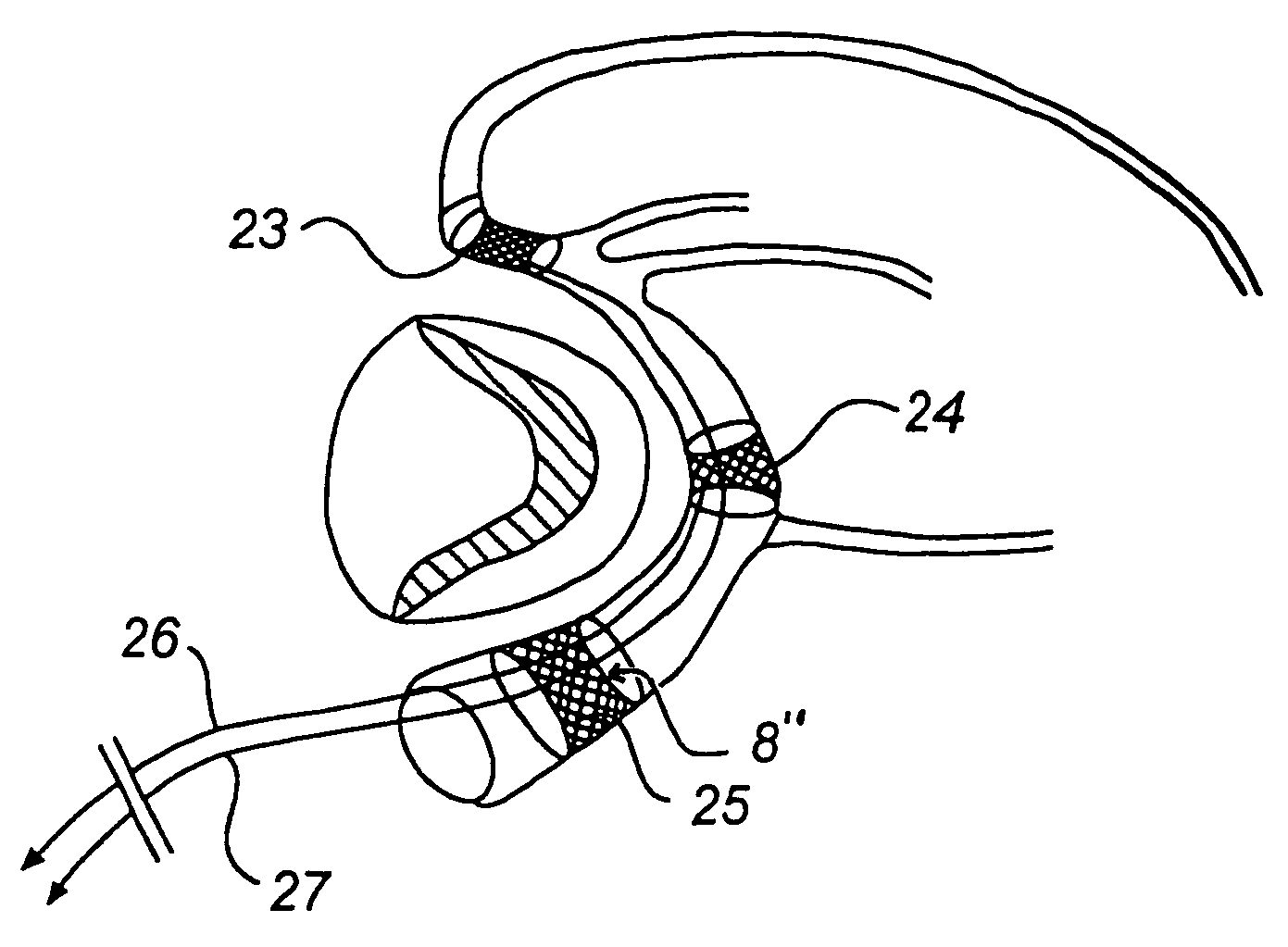
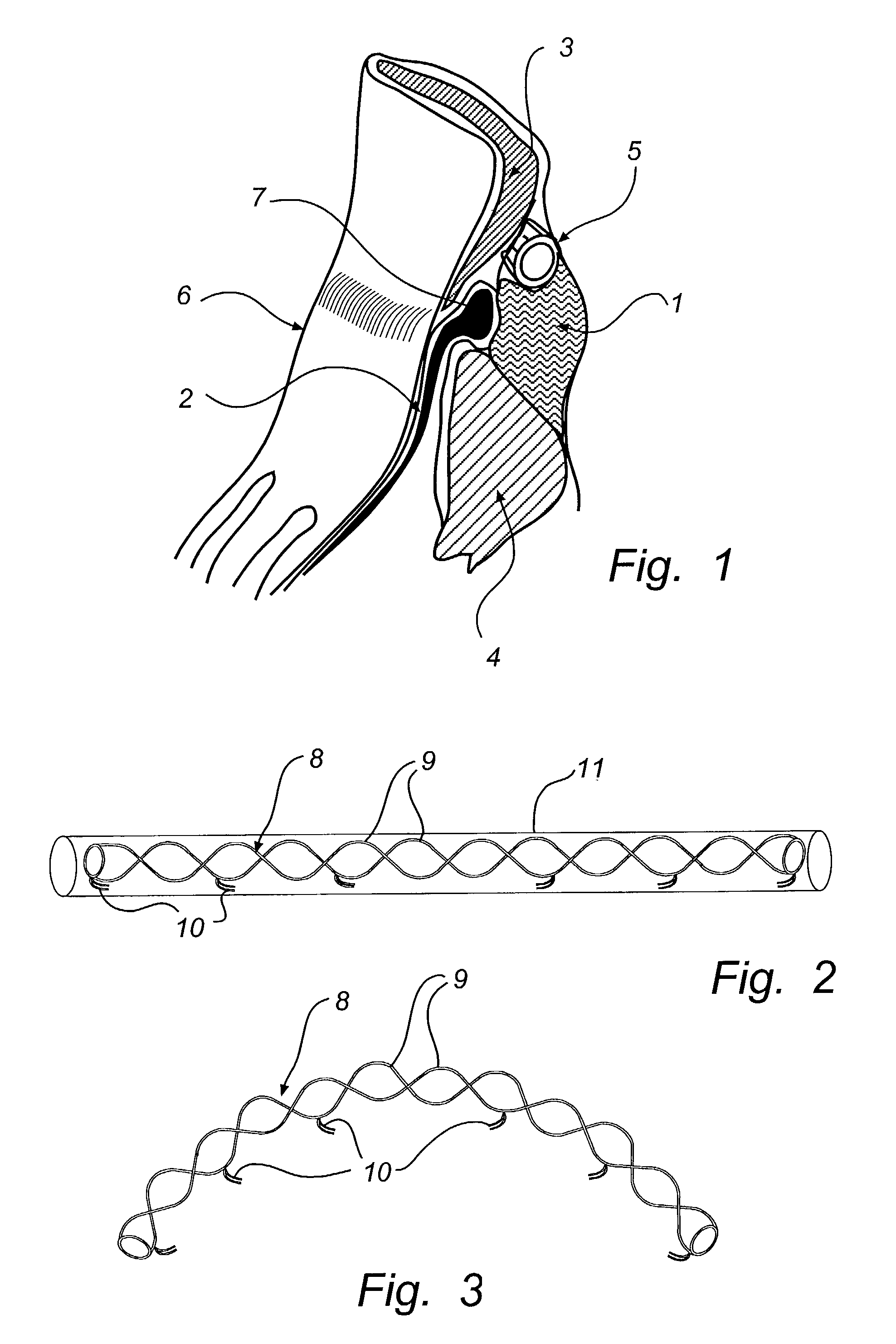
[0043]FIG. 1 is a cross-sectional view through the heart area of the posterior atrioventricular groove 1, which is filled with fatty tissue. It shows the posterior leaflet 2 of the mitral valve and the adjoining parts 3, 4 of the atrial myocardium and the ventricular myocardium. The coronary sinus 5 is shown close to the mitral annulus 6 and behind the attachment 7 of the posterior leaflet 2. Since the coronary sinus 5 substantially encircles the mitral annulus 6, a reduction of the radius of curvature of the bent coronary sinus 5 also will result in a diameter and circumference reduction of the mitral annulus 6.

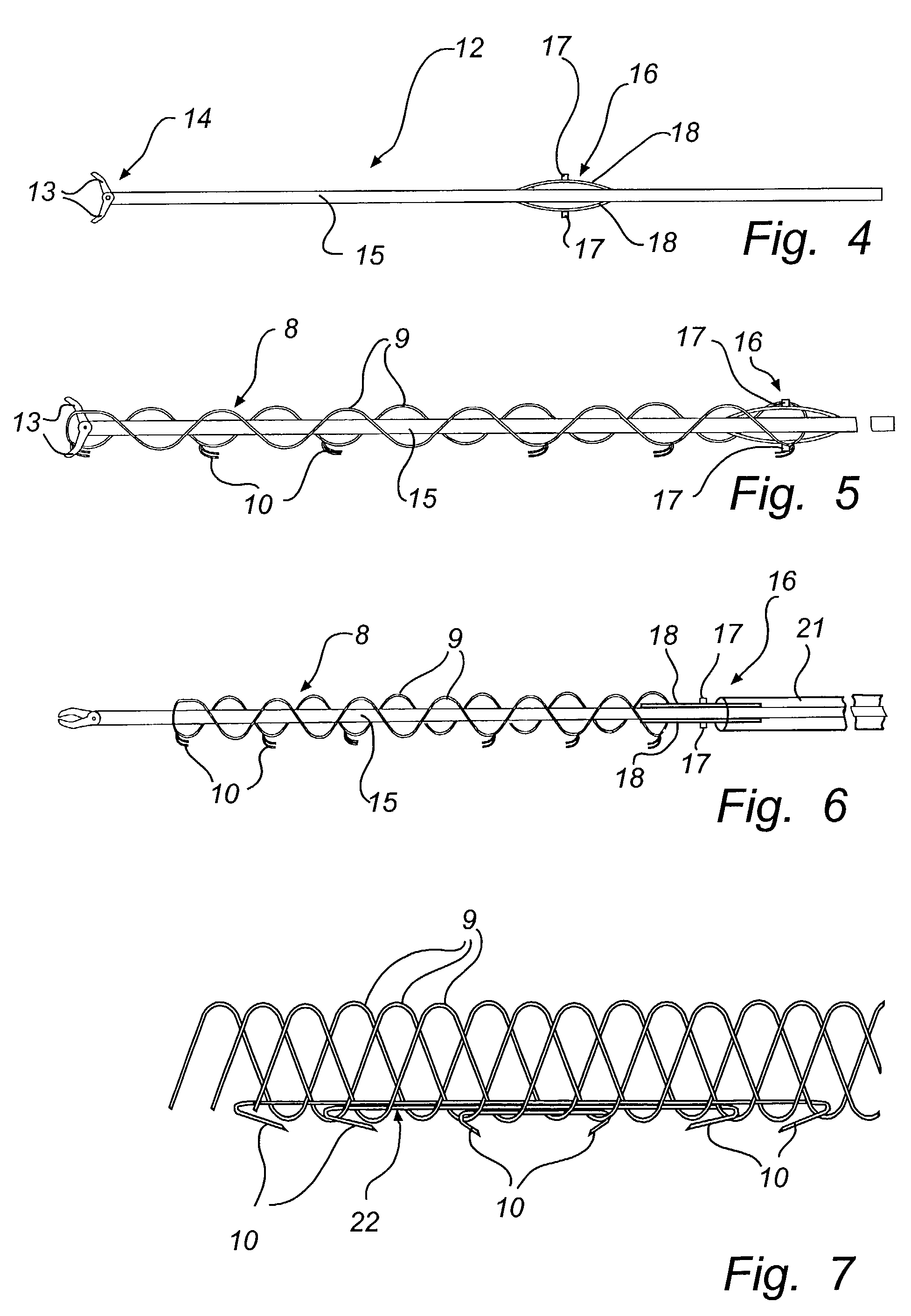
[0044]The device of FIG. 2 comprises an elongate body 8 made of memory metal, e.g. Nitinol, or other similar material which has a memory of an original shape, illustrated in FIG. 3, and can be temporary forced into another shape, illustrated in FIG. 2. This elongate body 8 comprises one, two or more memory metal strings 9 of helical or other shape so as to fit together and b...


PUM


Abstract

A method for treatment of mitral annulus dilatation comprises reducing the circumference of the mitral valve annulus. The method further comprises inserting an elongate body into the coronary sinus in the vicinity of the posterior leaflet of the mitral valve, fixing the position of the elongate body relative to the coronary sinus, and changing the shape of the elongate body in order to remodel the mitral valve annulus.

Description

CROSS REFERENCE TO RELATED APPLICATION[0001]This application is a division of U.S. patent application Ser. No. 09 / 775,677, filed on Feb. 5, 2001, which in turn is a continuation-in-part of U.S. patent application Ser. No. 09 / 345,475, filed Jun. 30, 1999, now U.S. Pat. No. 6,210,432.BACKGROUND OF THE INVENTION[0002]1. Technical Field of the Invention[0003]The present invention generally relates to a device and a method for treatment of mitral insufficiency and, more specifically, for treatment of dilatation of the mitral annulus.[0004]2. Description of the Prior Art[0005]Mitral insufficiency can result from several causes, such as ischemic disease, degenerative disease of the mitral apparatus, rheumatic fever, endocarditis, congenital heart disease and cardiomyopathy. The four major structural components of the mitral valve are the annulus, the two leaflets, the chordae and the papillary muscles. Any one or all of these in different combinations may be injured and create insufficienc...

Claims


Application Information

Patent Timeline
IPC IPC(8): A61F2/24A61F2/06A61F2/88A61F2/90
CPCA61F2/2451A61F2/90A61F2/88A61F2230/0078A61F2002/075A61F2220/0008A61F2/91
Inventor SOLEM, JAN OKIMBLAD, PER O
Owner JOMED
Why Eureka
Try Eureka