Ink jet device, ink jet ink, and method of manufacturing electronic component using the device and the ink

a technology ink, which is applied in the direction of printing, conductive pattern formation, capacitors, etc., can solve the problems of poor stability of ink jet printing, inability to use dielectric materials, magnetic materials, etc., and achieve poor stability and printing with ink jet

Inactive Publication Date: 2006-08-29
PANASONIC CORP
View PDF55 Cites 47 Cited by
  • Summary
  • Abstract
  • Description
  • Claims
  • Application Information

AI Technical Summary

Benefits of technology

[0025]The present invention provides an ink jet apparatus equipped with an ink-circulating / dispersing system, offering ink jet printing with stability. The system circulates ink and disperses it as required, thereby protecting the ink from forming precipitates and aggregates. During circulation, on the way to an ink-collecting tank via a tube, a portion of the ink containing powder is fed to a printer head and jetted onto a surface of a substrate to form a predetermined pattern. With this structure, the apparatus can cope well with ink having poor stability in terms of printing due to its easy-to-precipitate property, thereby offering ink jet printing with consistent quality onto a ceramic green sheet.

Problems solved by technology

These printing methods are suitable for mass-production; however, they are not good at producing small batches of a variety of products as a trend in recent years.
Therefore, they cannot be used as electrode material, dielectric material, or magnetic material.
Similarly, U.S. Pat. No. 4,894,092 introduces a heat-resistant pigment; this is also for coloring, so that it cannot be employed for electronic components.
U.S. Pat. No. 5,034,244 introduces a method of forming a heat-resistant substrate pattern for glass using an inorganic ceramic pigment; such a pigment-type ink cannot lend itself to production of electronic components.
Although the inks introduced in these suggestions are capable of printing and coloring such as marking electronic components made of ceramic, they cannot be used for an internal electrode, dielectric material, and magnetic material.
However, all these inks for coloring ceramics are not suitable for production of electronic components.
Employing an etching resist, however, increases a cost of manufacturing electronic components.
Conventional methods of ink jet printing and inks for ink jet printing, as described above, have not achieved a low-cost-production of electronic components.
In this process, if ink 1 has aggregates 6 therein, it can cause unstable jetting of droplets from the ink jet nozzle, which sometimes results in a failure to print.
This problem has lowered yields of electronic components.
Therefore, the ink, even if it belongs to the aforementioned area in FIG. 15, may not be handled with an ink jet apparatus available in the market.
In actuality, however, it is impossible to completely eliminate a powder having a particle size of 1 μm even after high classification.
Furthermore, it is difficult to break such a secondary particle into a smaller particle even being well dispersed, thereby inviting an increase in a processing cost for practical use.
Taking this into account, it is almost impossible, even in theory, to have stable dispersion in a solution having a low viscosity.
Such ink tends to have heterogeneous aggregation, so that it is difficult to obtain a stable dispersion.
Therefore, high concentration of powders in a solvent suddenly raises a viscosity of the solvent, thereby depriving fluidity from the solvent.
Whereas, in a case of ink used for producing electronic components, ceramic or metallic powder materials are required because an intended property cannot be obtained from dyes or metallic salts.
For this reason, it has been difficult to realize consistent printing quality.
Therefore, it has been difficult for the conventional apparatus to provide stable printing for long hours.
These aggregates and precipitates not only clog a head of an ink jet printer, but also invite unstable ink jetting and cause ill effect on a direction of ink jetting.
If the direction of jetting ink does not conform to a predetermined direction, faulty patterns—a deformed pattern, pin hole in solidly shaded areas in printing, or a short circuit in a wiring pattern—may result.
The ink required for producing electronic components, as described above, tends to have precipitates and aggregates, which has been an obstacle to stabilized quality in conventional ink jet printing.
Precipitates 14 and aggregates 14 can not only clog the printer head, but also invite unstable ink jetting and cause ill effect on the direction of ink jetting.
Therefore, if a direction of spouting ink does not conform to a predetermined direction, faulty patterns—a deformed pattern, pin hole in solidly shaded areas in printing, or a short circuit in a wiring pattern—may result.
However, up to now, an ink jet apparatus and ink available for such suggestions have not yet come into existence.
Therefore, they are no help for manufacturing electronic components.
For this reason, almost no demonstrations in which electronic components can be manufactured by ink jet printing has been made.
Even if prototypes of these inks are built and tested, clogging a nozzle may result due to the problems explained in FIGS. 16A and 16B.
However, metal powder and ceramic powder included in the ink immediately precipitated, thereby resulting in failure.
This attempt invited clogging of the printer head caused by particles of the ink precipitated in the printer head.
As is proved by this attempt, an ink jet apparatus capable of coping with ink having high-concentration, high-density, and low-viscosity that is typified by ink for electronic components to offer reliable printing, has not yet been on the market.
The inventors demonstrated that a solvent of ink penetrates into a ceramic green sheet and causes a short circuit, thereby decreasing a yield of a product.
That is, in a case of employing a ceramic green sheet with a thickness of less than 20 μm, penetration of a solvent of ink through such a thin sheet can cause a short circuit, even if electrodes can be formed by ink jet printing.
Inks employing dye and a metallic salt have been conventionally suggested; however, no suggestion has been made about an ink jet apparatus that can offer reliable printing using ink easily forming precipitates and aggregates, such as ink for manufacturing electronic components.
Even if such inks for electronic components as a completed product are filtered by an extremely fine filter, precipitation or aggregates in the ink jet apparatus may result.
This fact easily invites clogging of a printer head or ink-spouting section, and as a result, it has been difficult to obtain printing with stability.
Such inks, however, are intended for coloring, not for manufacturing electronic components such as LC filters and high-frequency electronic components.
Besides, in a process of producing laminated ceramic electronic components, and in a case that ink for electrodes is applied onto a thin ceramic green sheet with a thickness of less than 20 μm, a conventional ink jet apparatus has not been successful in providing printing quality with stability.
Such inks, due to their property of easily forming precipitates and aggregates, tend to clog the head or the ink-spouting section of an ink jet printer, thereby resulting in inconsistent printing.

Method used


Image

  • Ink jet device, ink jet ink, and method of manufacturing electronic component using the device and the ink
  • Ink jet device, ink jet ink, and method of manufacturing electronic component using the device and the ink
  • Ink jet device, ink jet ink, and method of manufacturing electronic component using the device and the ink

Examples


first embodiment

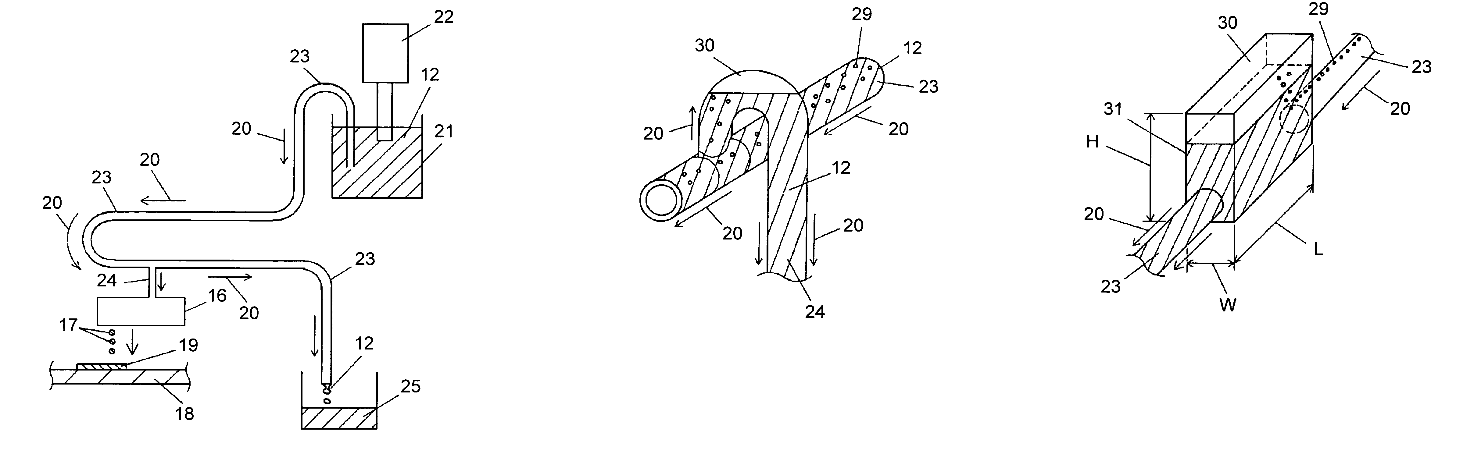
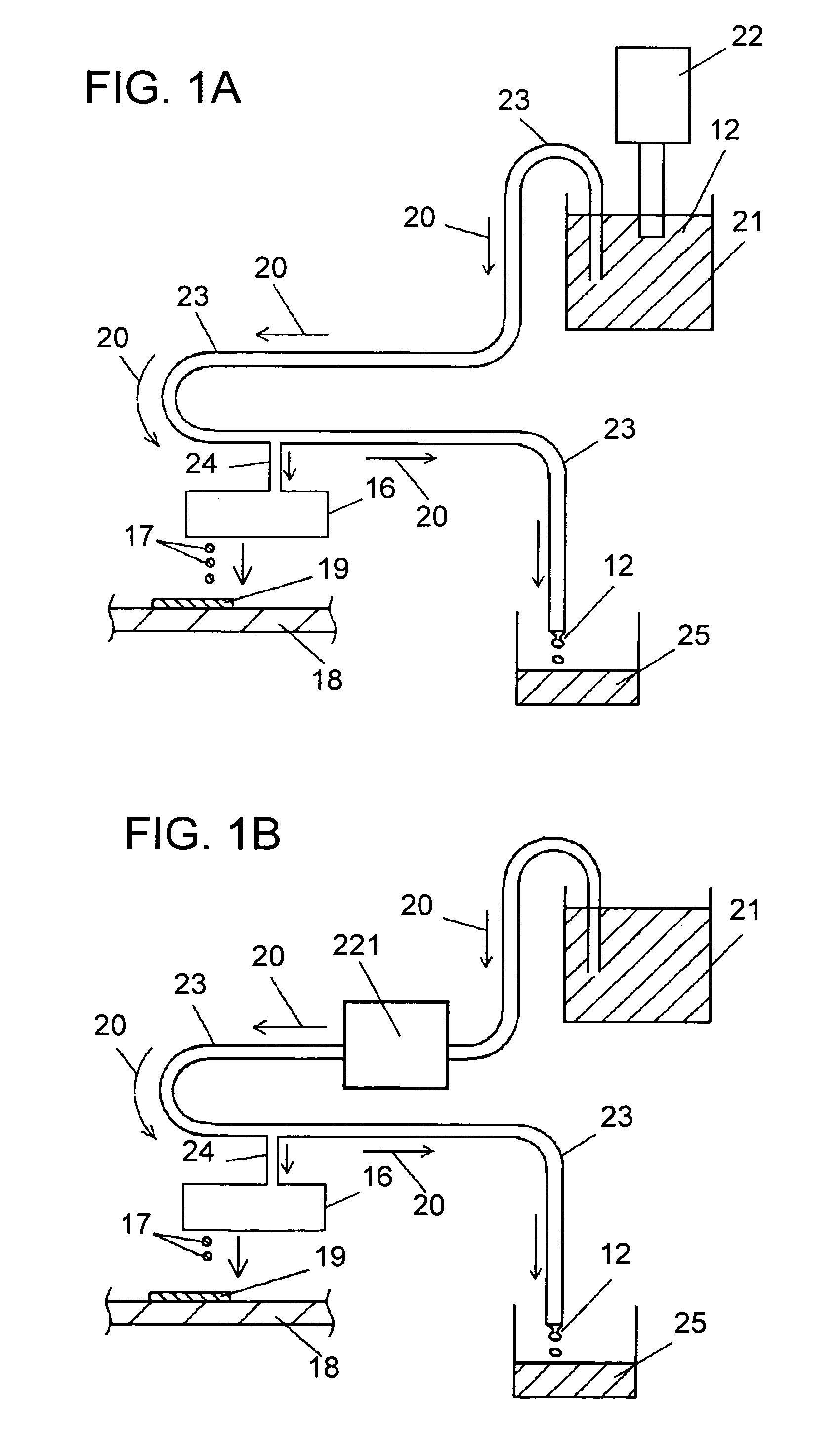
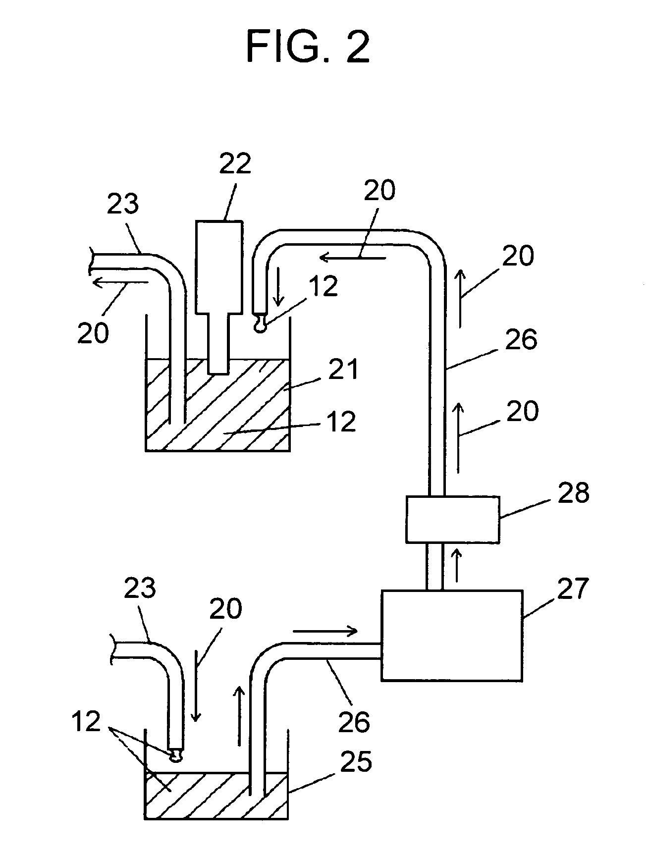
[0043]An ink jet apparatus and its ink-supplying system of a first embodiment of the present invention will be described, with reference to FIG. 1A. An interior of ink tank 21 of FIG. 1A is filled with ink 12. Dispersing unit 22 disperses ink 12 in ink tank 21 as required. The ink stored in tank 21 flows by its own weight via first tube 23 into ink collecting tank 25. Setting ink tank 21 to a position higher than that of ink-collecting tank 25 can provide the ink with natural flow, on a principle of a siphon, without using a pump or the like. Through the process above, ink 12 in tank 21 flows through first tube 23 and drips down into tank 25. According to the present invention, ink 12 has constant flow through first tube 23 and some of the ink to be used for printing is carried through second tube 24 to printer head 16. Printer head 16 filled with ink 12 jets out the ink on a “drops-on-demand” basis in response to an external signal (not shown) to form droplets 17. Droplets 17 land ...

second embodiment

[0057]An example in which removing fine bubbles mixed into the ink further improves printing stability is explained. In a case that the ink jet apparatus having piezoelectric printer head 16 is employed, it is known that bubbles entered into the ink reside and grow in the printer to absorb vibration energy of piezoelectric elements and cause unstable printing (see P. 202–206 of “Ink jet printing technology and materials” compiled under the supervision of Takeshi Amari, professor at Chiba Univ., published from CMC Publishing Co. 1998). In particular, the present invention has a structure in which dispersing unit 22 is fixed to ink tank 21. A problem is that employing a high-speed rotating homogenizer or ultrasonic dispersing unit for dispersing unit 22 can entrain fine bubbles into ink tank 21. For example, in the case of using the high-speed rotating homogenizer, bubbles captured from a surface of the ink are often observed; similarly, in the case of the ultrasonic dispersing unit, ...

third embodiment

[0066]In a third embodiment, a more detailed explanation of a distinctive feature of the present invention—circulation and dispersion of ink—will be given hereinafter. FIGS. 6A and 6B show data obtained by measurement of precipitation velocity of practically used ink for manufacturing electronic components. In particular, the ink for manufacturing electronic components has an extremely easy-to-aggregate property, thereby it tends to form precipitates. Here will be given a more detailed explanation of the aforementioned property, referring to FIGS. 6A and 6B. In FIG. 6A, ink tank 21 is filled with ink 12. Dispersing unit 22 is put into ink 12, with a switch being OFF(switch off). When dispersing unit 22 is kept in OFF mode, i.e., the ink is left with no movement, as shown in FIG. 6A, clear layer 36 appears in ink 12 with passage of time. Clear layer 36 grows thicker as time goes by. FIG. 6B illustrates a process of developing each clear layer in three types of ink for manufacturing e...


PUM

PropertyMeasurementUnit
inner diameteraaaaaaaaaa
viscosityaaaaaaaaaa

Abstract

Here disclosed is an ink jet apparatus having an ink-circulating / dispersing function. The apparatus provides ink with dispersion as required, and circulates the ink through a tube to an ink-collecting tank. During this circulation, a required amount of the ink is fed to a printer head to form a predetermined pattern on a surface of a substrate. By virtue of the circulating / dispersing function, the apparatus can cope well with easy-to-aggregate ink having poor stability in terms of printing, thereby protecting a printer head or an ink-spouting section from clogging during ink jet printing. Such stabilized ink jet printing contributes to manufacturing highly reliable electronic components with an increased yield of products.

Description

TECHNICAL FIELD[0001]The present invention relates to a method of manufacturing ceramic electronic components such as laminated ceramic capacitors, high-frequency electronic components, filters, and multilayer substrates. The method uses an ink jet apparatus, which jets ink in a reliable manner to form the foregoing electronic components without contact between this printing device and these objects to be printed.BACKGROUND ART[0002]Conventionally, an internal electrode and a ceramic layer used for ceramic electronic components have mainly been manufactured by printing methods using printing plates, such as screen printing and gravure printing. These printing methods are suitable for mass-production; however, they are not good at producing small batches of a variety of products as a trend in recent years. Responding to such demands, ink jet printing for manufacturing ceramic electronic components has been suggested as a new printing method.[0003]First of all, ink typically used for ...

Claims


Application Information

Patent Timeline
Patent Type & Authority Patents(United States)
IPC IPC(8): B41J2/175B41J2/19H01B1/16H01G4/00H05K3/12
CPCB41J2/17509B41J2/175
Inventor NAKAO, KEIICHIOKINAKA, HIDEYUKI
Owner PANASONIC CORP
Why Eureka
Try Eureka