Flash vapor sampling for a trace chemical detector

a detection instrument and vapor sampling technology, applied in the direction of instruments, resistance/reactance/impedence, withdrawal sample devices, etc., can solve the problems of increasing the cost of absorbers, increasing so as to increase the emission of target vapor, and reduce the difficulty of concentrating.

Inactive Publication Date: 2006-08-29
LEIDOS SECURITY DETECTION & AUTOMATION INC
View PDF4 Cites 31 Cited by
  • Summary
  • Abstract
  • Description
  • Claims
  • Application Information

AI Technical Summary

Benefits of technology

[0014]Apparatus may be employed for guiding and concentrating the photon beam from the light source towards a place on the target surface where gas sampling is more efficiently being performed in order to minimize the power consumption, heat primarily the target surface of interest, and maximize the lifetime of the light source. This apparatus may be in the form of one or more lenses, one or more mirrors, fiber optic cable, or some combination of these. An example may include a parabolic mirror combined with a nearly point source of light. With the point source situated near to the focal point of the mirror, a substantially parallel photon beam results, which can then be directed at the desired location on the target surface.
[0016]The source of light may be pulsed or keyed to form a pulse less than 100 milliseconds in duration. Pulsed light has the advantage of conserving energy and avoiding overheating of the target surface. Pulsed light has the further advantage of warming the target surface in a very short time period, thus causing the emitted target vapor to mix with a smaller portion of ambient air before being drawn into the gas sampling orifice. This enhances the target vapor concentration by reducing dilution. A further desirable feature is that the pulsed light source is off when not in use, thus saving energy. A continuous output light source requires time to come to stable operating conditions and thus is slow to pulse. An alternate embodiment would be to combine a shutter with a continuous output light source in order to simulate a pulsed source, but a naturally pulsed light source is usually brighter than a continuous light source with a shutter for an equal average power consumption. Equivalently, a continuous source of light may be pulsed on with a pulse duration less than 100 milliseconds, and this is sometimes referred to as “keyed”. An example of such a source of light is a light emitting diode or a plurality of such diodes, which emit photons only when a voltage pulse is applied. A laser is less desirable for this application in that the laser beam is typically very small in cross section and must be scanned across a surface in a raster pattern to illuminate a large area. Lasers are also more expensive than xenon lamps or light emitting diodes.
[0018]In one embodiment, a high brightness pulsed lamp, such as a xenon-filled lamp, is used to illuminate the adsorbing surface for a time period less than 100 milliseconds, for example, less than 1 millisecond. The energy transmitted by the pulse of photons from the lamp to the target surface may be much smaller than that required to heat the entire substrate of the target surface to a given temperature. Still, the surface layer of the target surface, which only includes a few hundred monolayers of atoms, may not conduct this sudden influx of energy away instantaneously, and thus the target surface may momentarily become relatively warm. The effect might last only for a few milliseconds before thermal conduction dissipates the energy into the substrate of the target material, and the surface layers cool off.

Problems solved by technology

The method of concentrating using an absorbent substance tends to be relatively slow to implement and is subject to variations in the skill of the operator.
Additionally, while the absorber is relatively low in cost, the process of taking a great many samples becomes expensive in that the absorber generally should only be used once to ensure consistent results.
Examples may include, but not be limited to, sampling of vapor from complex surfaces that contain many holes, crevices, or deep depressions, textured materials such as cloth, people and animals that prefer not to be rubbed by absorbent material, large three dimensional objects, surfaces that must be sampled in a short time, and surfaces in which surface rubbing by human operators is inconvenient or expensive.
In addition, it has been observed that the sampling orifice may become contaminated with vapor-emitting particles if the sample inadvertently contacts the orifice.
Such contamination is particularly difficult to remove in a short period of time, thus preventing continuous operation of the instrument.
However, besides the interference with the performance of the instrument for measuring trace vapors caused by high velocity flow, this method dilutes the concentration of the desired sample vapor by mixing in a much larger volume of ambient gas.
Therefore, the sensitivity of the instrument may decline if the sample gas flow rate is increased excessively.
Warming surfaces at a distance using an oven is generally not very efficient.
While warmed gas can be blown onto a distant surface, for example with a “heat gun”, when the target surface is a living person or animal, this may not be an acceptable option.
Additionally, many surfaces cannot tolerate excessive heating and may be damaged.

Method used


Image

  • Flash vapor sampling for a trace chemical detector
  • Flash vapor sampling for a trace chemical detector
  • Flash vapor sampling for a trace chemical detector

Examples


Embodiment Construction

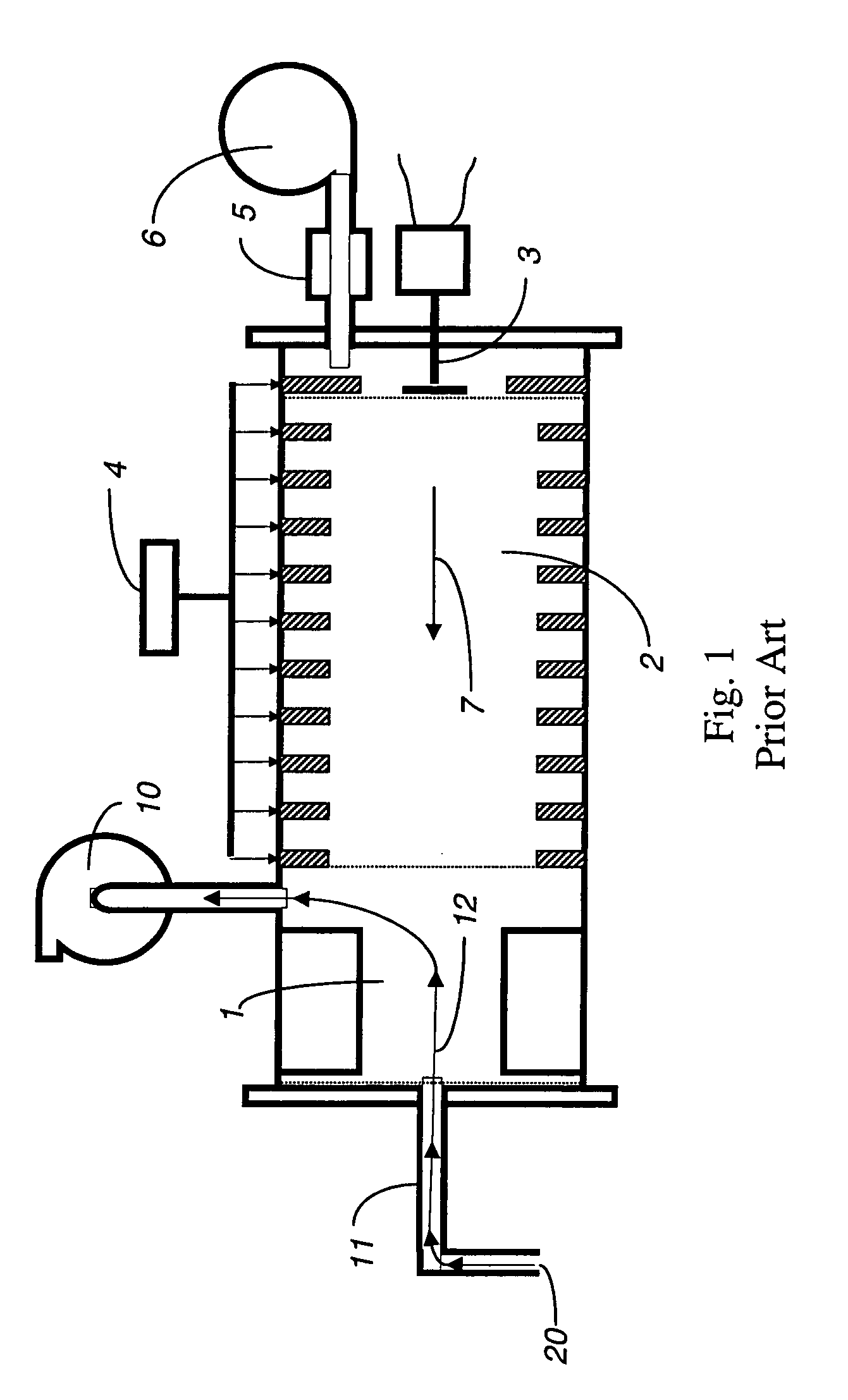
[0026]An IMS is illustrated in FIG. 1. While various embodiments may differ in details, FIG. 1 shows basic features of an IMS that may be used in connection with the system described herein. The IMS includes an ion source 1, a drift tube 2, a current collector 3, a source of operating voltage 4 and a source of purified drift gas 5, possibly with its own gas pump 6. An IMS may already include a gas pump for gas sampling 10 and a tubular connection 11 between the ion source 1 and an external gas sampling inlet 20 that includes an orifice. Gas flow for the drift gas 7 moves through the drift tube 2. Sampling gas flow 12 moves from the external gas sampling inlet 20 through the tubular connection 11 and ion source 1 to the gas sampling pump 10.

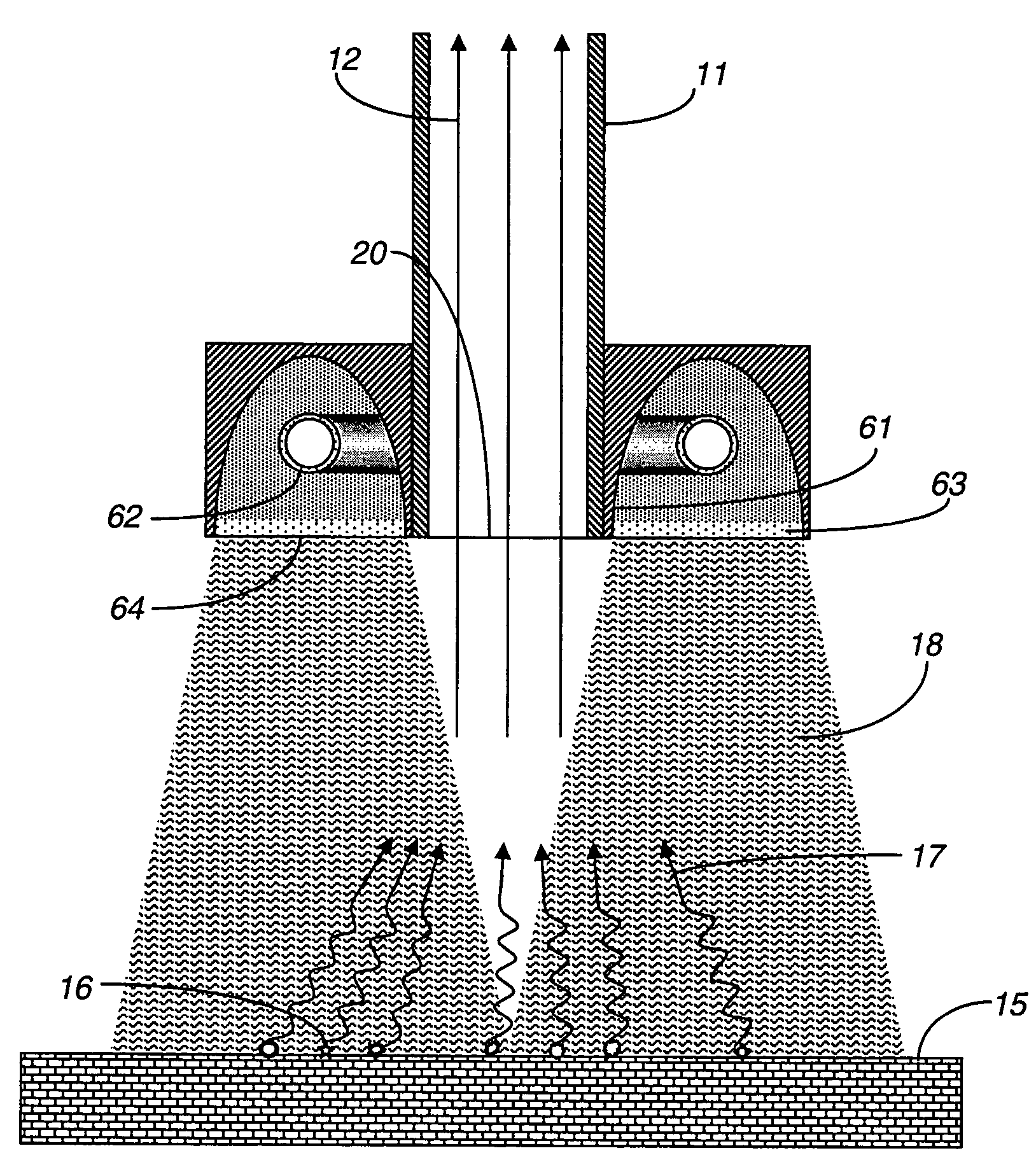
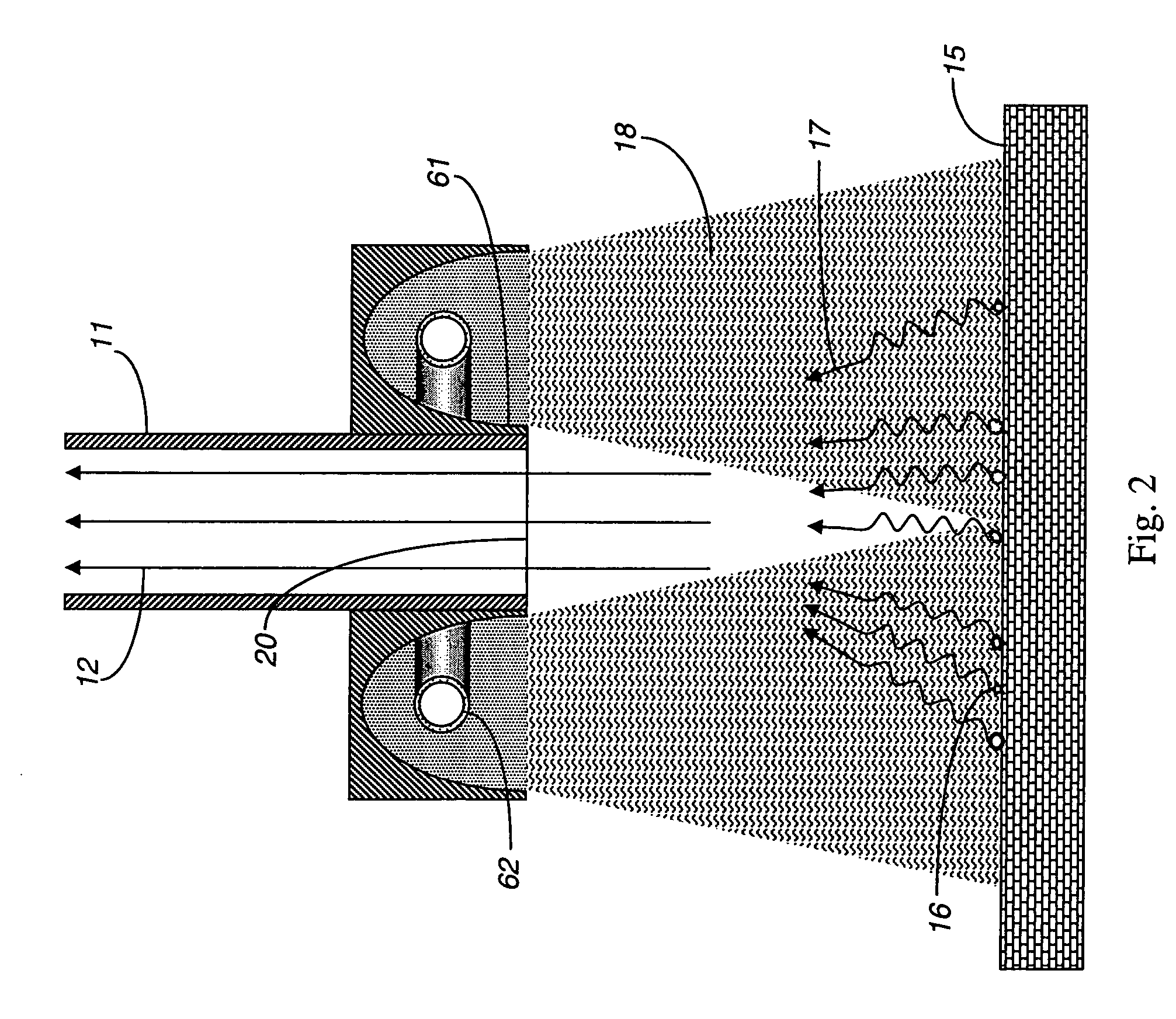
[0027]FIG. 2 shows an exemplary embodiment for a system using an electrical discharge in a gas within a pulsed light lamp 62 provided proximal to the gas sampling inlet 20 that heats the target surface 15 in conjunction with the gas sampling syste...


PUM

PropertyMeasurementUnit
timeaaaaaaaaaa
timeaaaaaaaaaa
wavelengthsaaaaaaaaaa

Abstract

The presence of trace molecules in air is often determined using high sensitivity gas sensing instruments, such as an ion mobility spectrometer. Such devices are commonly utilized in the fields of explosives detection, identification of narcotics, and in applications characterized by the presence of very low airborne concentrations of organic molecules of special interest. The sensitivity of such instruments is dependent on the concentration of target gas in the sample. The sampling efficiency can be greatly improved when the target object is warmed, even by only a few degrees. A directed emission of photons in the range between infrared and ultraviolet light can be used to significantly enhance vapor emission.

Description

CROSS-REFERENCE TO RELATED APPLICATIONS[0001]This application is a continuation-in-part of U.S. patent application Ser.No. 10 / 349,491 filed on Jan. 22, 2003 now U.S. Pat. No. 6,828,795, which claims priority from U.S. patent application Ser. No. 10 / 295,039 filed on Nov. 14, 2002, which claims priority from U.S. Provisional Application No. 60 / 357,394, filed Feb. 15, 2002, U.S. Provisional Application No. 60 / 357,618, filed Feb. 15, 2002, and U.S. Provisional Application No. 60 / 363,485, filed Mar. 12, 2002, all of which are incorporated herein by reference. This application is also a continuation-in-part of U.S. patent application Ser. No. 10 / 853,563, filed May 25, 2004, which claims priority from U.S. Provisional Patent Application Ser. No. 60 / 473,649, filed May 28, 2003, both of which are incorporated herein by reference.FIELD OF THE INVENTION[0002]This invention relates to a trace chemical vapor detection instrument that detects chemicals present as vapors in air or other gases, or ...

Claims


Application Information

Patent Timeline
Patent Type & Authority Patents(United States)
IPC IPC(8): G01R27/04G01N25/00G01N27/62
CPCG01N1/22G01N1/4022B01B1/005G01N27/622G01N2001/028
Inventor BELYAKOV, VLADIMIR V.BUNKER, STEPHEN N.
Owner LEIDOS SECURITY DETECTION & AUTOMATION INC
Why Eureka
Try Eureka