Spectroscopic systems and methods

a spectroscopic system and system technology, applied in the field of spectroscopic systems, can solve the problems of significant delay, slow measurement, and limit the rotation speed of moving parts,

Active Publication Date: 2006-08-29
DELTA SEARCH LABS
View PDF14 Cites 32 Cited by
  • Summary
  • Abstract
  • Description
  • Claims
  • Application Information

AI Technical Summary

Problems solved by technology

Current wavelength-selecting devices, such as monochromators, have some inherent drawbacks:1. Measurements are usually slow.
The inertia of the moving parts (gratings, gear-reduction mechanisms, etc) usually limits the speed of rotation of the moving parts.
For the continuous scan method, significant delay occurs as a result of the need to let the grating or filter come to a stop and start moving in the opposite direction with precision and without causing large vibrations.
The rotary stage of such instruments is typically not precise enough for most high-SNR or low-noise applications, requiring high spectral repeatability such as quantitative spectroscopy measurements Other scanning systems (e.g., thermal and opto-acoustic systems) have their own inherent limitations in regard to their ability to reliably and accurately reproduce a specified wavelength.3. Systems designed for high SNR applications are expensive due to a need for high-precision mechanical and electrical components.4. Current wavelength-selecting systems are highly sensitive to mechanical vibrations.
Such a method has the disadvantage that the sources of noise regardless of their respective frequencies add on to the resulting signal, negatively impacting the signal-to-noise ratio (SNR).
1. A mechanical chopper adds complexity to a spectroscopic system.
Thus, modulation using a mechanical chopper can add significant cost to a spectroscopic system.2. Mechanical choppers are typically bulky and difficult to miniaturize.3. Measurement becomes slower, because the wavelength-scanning device needs to “wait” for the light chopper to produce enough turns / modulations before proceeding to the next wavelength segment.
This type of chopping device is usually limited to only a few hundred hertz.4. Modulation using a mechanical chopper does not eliminate the low frequency (close to DC frequency) stability error, such as those caused by temperature variations or power drifts.

Method used


Image

  • Spectroscopic systems and methods
  • Spectroscopic systems and methods
  • Spectroscopic systems and methods

Examples


example

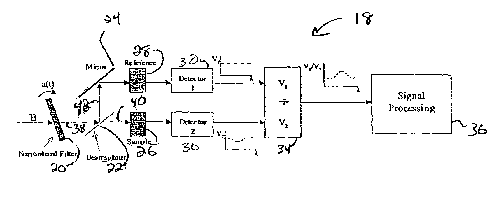
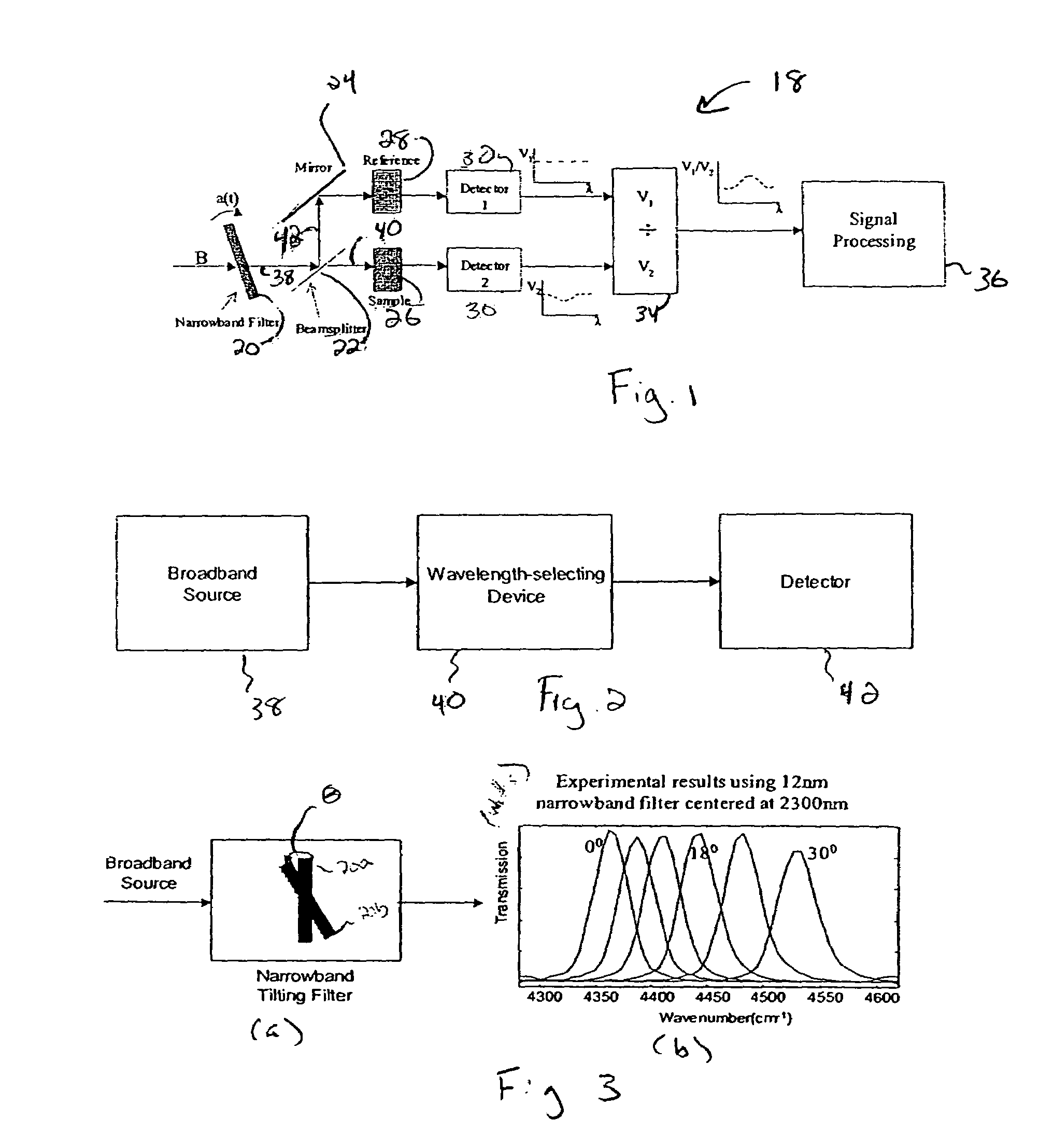
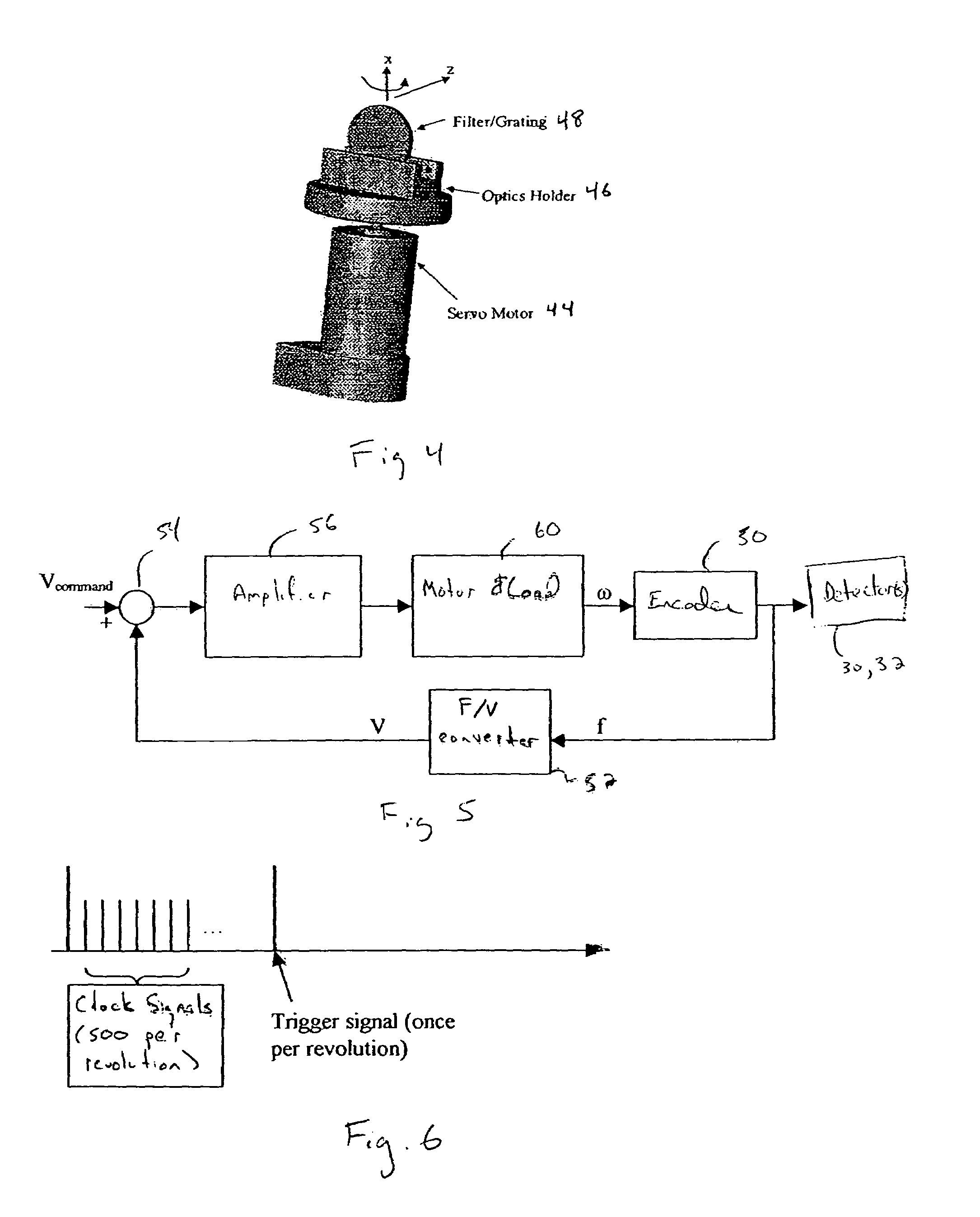
[0072]One can construct embodiments of the present invention according to FIGS. 1, 4 and 5 using the following components. One can use a 250W tungsten-halogen source such as model #LSH-T250 available from Jobin Yvon, Inc. of New Jersey, USA, as a broadband source (not shown in FIG. 1). One can use a narrow-band transmitting filter such as model #F12-2300-3 available from CVI Laser Corp. of New Mexico, USA as an interference filter portion of the CSWS device 20. One can use a BK7 glass (90% transmitted for the main sample, and 10% reflected for the reference sample), available from most optical component distributors and / or manufacturers such as CVI Laser Corp. of New Mexico, USA, as the beamsplitter 22. One can use a brush motor with integrated position encoder such as model #8324S005 available from Pittman of Pennsylvania, USA as the servo motor 44. One can use a 12A 80V brush motor amplifier such as model #12A8K available from Advanced Motion Controls of California, USA as the mot...


PUM

PropertyMeasurementUnit
angle of incidenceaaaaaaaaaa
angleaaaaaaaaaa
solid angleaaaaaaaaaa

Abstract

The present invention relates to spectroscopic methods and systems for collecting electromagnetic radiation from an object using a continuously-spinning wavelength-selecting (CSWS) device, e.g., an interference filter(s) or grating. One embodiment of the invention provides a spectroscopic system for collecting electromagnetic radiation from a target. The spectroscopic system has at least one beam of electromagnetic radiation that interacts with the target. The system includes a continuously spinning wavelength-selecting (CSWS) device, e.g., a continuously spinning interference filter / grating driven by a DC motor, in the path of the at least one beam. The device filters the radiation with regard to wavelength to produce filtered radiation. The system further includes at least one detector in the path of the at least one beam for detecting the filtered radiation.

Description

RELATED APPLICATIONS[0001]This application claims priority to, and the benefit of, earlier filed U.S. Provisional Application Ser. No. 60 / 469,171, filed May 9, 2003, entitled “SPECTROSCOPIC SYSTEM WITH CONTINUOUSLY-SPINNING WAVELENGTH-SELECTING DEVICE.”BACKGROUND OF THE INVENTION[0002]This invention relates to a spectroscopic system having an improved spectral signal-to-noise ratio and a simpler configuration involving fewer mechanical parts than current grating-based instruments.[0003]At a minimum, a spectrometer (e.g., a Raman, fluorescence, absorption or reflectance spectrometer) includes a light source, a photo-detector and a wavelength-selecting device. A wavelength-selecting device is often called a spectroscope. Depending on the application, the sample can be inserted between the source and the spectroscope or between the spectroscope and the detector.[0004]There are different types of spectrometers. One type of spectrometer is a wavelength-scanning instrument. A wavelength-s...

Claims


Application Information

Patent Timeline
Patent Type & Authority Patents(United States)
IPC IPC(8): G01J3/42G01N21/25G01J3/06G01J3/12G01J3/28G01J3/433G01N21/27G01N21/31G01N21/35
CPCG01J3/06G01J3/2889G01J3/42G01J3/433G01N21/255G01N21/274G01N21/276G01N21/3504G01J2003/062G01N2021/317G01J2003/1243
Inventor SAPTARI, VIDI A.YOUCEF-TOUMI, KAMAL
Owner DELTA SEARCH LABS
Why Eureka
Try Eureka