Magnetic head, method for recording/reproducing tape-like magnetic recording medium, and rotary magnetic head mechanism

a magnetic recording medium and magnetic head technology, applied in the direction of maintaining the head carrier alignment, manufacturing head surface, instruments, etc., can solve the problems of tape thickness loss, head gap b>103, and wear

Inactive Publication Date: 2006-08-29
SONY CORP
View PDF23 Cites 0 Cited by
  • Summary
  • Abstract
  • Description
  • Claims
  • Application Information

AI Technical Summary

Benefits of technology

[0018]The present invention is made to solve the problems in the above described conventional technology, and its object is to provide the magnetic head and the recording and reproducing method for the tape magnetic recording medium and the rotary magnetic head mechanism which are capable of extending the life of the head and the life of the tape by maintaining an excellent contact state between the head and the tape medium while reducing the contact pressure so as to reduce wear, and which are applicable to the tape medium of the magnetic resistance effect type head.
[0023]The magnetic head according to claim 3 of the present invention is the head according to claim 1 or claim 2, wherein the surface for facing the tape magnetic recording medium has the smooth curved surface having the curvature gentler than the curvature of the rotary drum and therefore the pressure reduction effect depends on the shape or smoothness of the surface and, when the gentleness is the same, the pressure reduction effect on the surface having a gentle smooth curvature becomes great. Accordingly, this enables the operation where the tape magnetic recording medium is brought into contact with the magnetic head by pressure reduction effect without bringing it into contact with the rotary drum or the operation where the tape magnetic recording medium is brought into contact with the rotary drum by light contact pressure, while bringing it into contact with the magnetic head by desired contact pressure generated by much stronger pressure reduction effect.
[0030]According to the above described configuration, the projection of the magnetic head from the cylindrical surface of the rotary drum easily makes the tape magnetic recording medium contact the projected magnetic head, whereby an air flow formed in the vicinity of the rotary drum accompanied by the rotation is prevented from flowing into the smooth flat surface by the tape magnetic recording medium. On the other hand, pressure reduction according to Bernoulli's law is generated by hydrodynamic interference between the smooth flat surface and the approached tape magnetic recording medium and this pressure reduction is effectively performed by preventing the air flow in the vicinity of the rotary drum from flowing into the smooth flat surface as described above so that the tape magnetic recording medium rapidly approaches and contacts the surface. In this way, the contact is made at a shorter distance, thereby making the magnetic head compact.
[0036]According to the above described configuration, by the action of negative pressure generated on the concave channel, the passing tape magnetic recording medium is pulled and the locus moves inward, with the magnetic head projected from the cylindrical surface, so that the tape magnetic recording medium more effectively approaches and contacts a magnetic head end portion, and the air flow drawn out from the channel is controlled or shut out and the air flow formation on the magnetic head is effectively controlled.
[0038]In the rotary magnetic head according to claim 9 is the head according to claim 5, 6, 7 or 8, the above described surface facing the above described tape magnetic recording medium is a smooth curved surface having the curvature gentler than the curvature of the above described rotary drum and therefore the above described pressure reduction effect depends on the shape or gentleness of the surface and, when the gentleness is the same, the pressure reduction effect on the surface having a smooth curvature becomes great. This enables the operation where the tape magnetic recording medium is brought into contact with the magnetic head by pressure reduction effect without bringing it into contact with the rotary drum or the operation where the tape magnetic recording medium is brought into contact with the rotary drum by light contact pressure, while bringing it into contact with the magnetic head by desired contact pressure generated by much stronger pressure reduction effect.

Problems solved by technology

Moreover, a tape thickness becomes thinner from the tape thickness of approximately 10 to 16 μm adopted in the conventional editing machine because of the demand for a compact tape cassette and a long time recording and reproducing.
However, as a result of pressing the magnetic tape medium 105 compulsively against the convex magnetic head 104 as described above, the problems arise that the head gap 103 is worn and the head gap life is shortened.
Other problems also arise that the magnetic surface of the magnetic tape medium 105 is also worn and the tape life is shortened due to non-reversal deformation.
However, the configuration where the initial gap depth is deeply set presents the problems in that the improvement of sensitivity has a limit, a high density recording is controlled and a high density reproducing has a limit.
Moreover, it did not have any effect on solving the problem of the shortened life of the tape.
Moreover, it also does not realize a means with which an MR head and a GMR head of the magnetic resistance effect type (or magnetic flux response type) having a configuration where the magnetic field changes on the recording medium are detected with an extremely shallow gap by utilizing the magnetic resistance effect, which are mainly applied in a hard magnetic disc drive (HDD), can be applied in the tape magnetic recording medium in place of the magnetic head based on the above described magnetic induction principle.

Method used


Image

  • Magnetic head, method for recording/reproducing tape-like magnetic recording medium, and rotary magnetic head mechanism
  • Magnetic head, method for recording/reproducing tape-like magnetic recording medium, and rotary magnetic head mechanism
  • Magnetic head, method for recording/reproducing tape-like magnetic recording medium, and rotary magnetic head mechanism

Examples


first embodiment

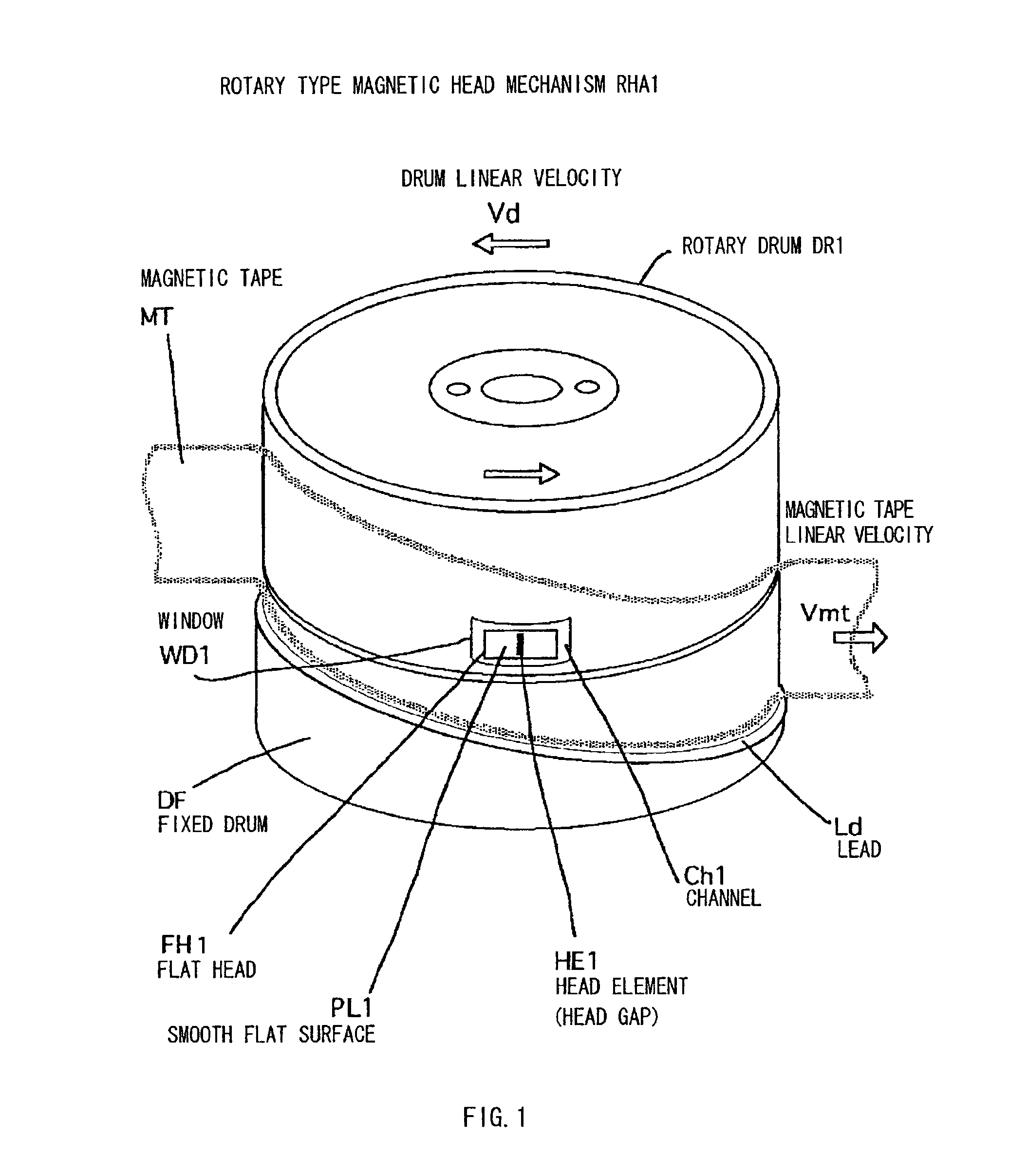
[0039]FIG. 1 is a schematic perspective view showing principal components of a rotary magnetic head mechanism of the present invention.

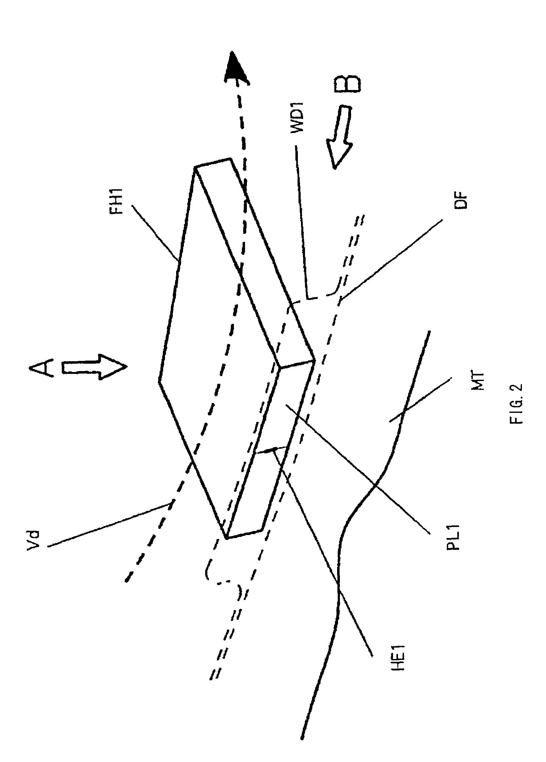
[0040]FIG. 2 is an explanatory drawing of the configuration of a magnetic head shown in FIG. 1, which is one embodiment of the present invention.

[0041]FIG. 3 is a diagram viewed from the direction of arrow A in FIG. 1.

[0042]FIG. 4 is a diagram viewed from the direction of arrow B in FIG. 1.

[0043]FIG. 5 is an explanatory drawing of a loading state of a magnetic tape when a rotary drum as shown in FIG. 1 rotates.

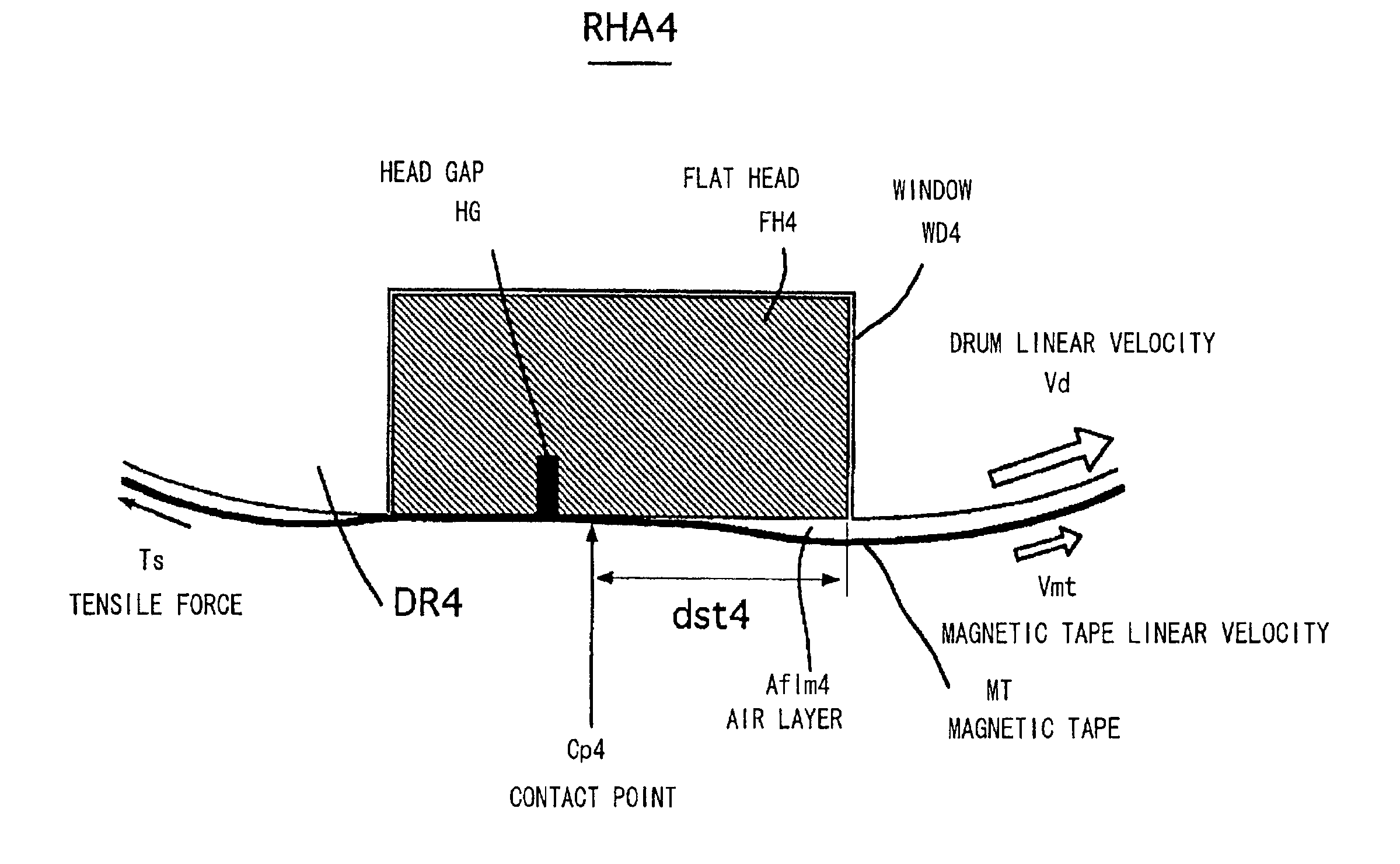
[0044]FIG. 6 is a principle explanatory drawing of a rotary magnetic head mechanism of the present invention.

third embodiment

[0045]FIG. 7 is a principle explanatory drawing of the rotary magnetic head mechanism of the present invention.

fourth embodiment

[0046]FIG. 8 is a principle explanatory drawing of the rotary magnetic head mechanism of the present invention.


PUM


Abstract

To provide a magnetic head, a recording / reproducing method for a tape magnetic recording medium and a rotary magnetic head mechanism. A flat head FH1 is mounted on a rotary drum DR1 capable of allowing a magnetic tape MT to run thereon, and a smooth flat surface PL1 that faces the magnetic tape MT and produces hydrodynamic interference with the magnetic tape MT is provided on a flat head FH1, and a head element HE1 that contacts the magnetic tape MT and produces magnetic interference is provided in the area where the magnetic tape MT contacts the smooth flat surface PL1.

Description

[0001]This Application is a 371 of PCT / JP01 / 01488 Feb. 28, 2001.TECHNICAL FIELD[0002]The present invention relates to a magnetic head, a recording and reproducing method for a tape magnetic recording medium, and a rotary magnetic head mechanism.BACKGROUND ART[0003]As an apparatus for recording and reproducing signals on / from a tape magnetic recording medium, a rotary drum type of video cassette recorder apparatus is widely used wherein a track is formed at an inclined angle for record on the tape magnetic recording medium by the magnetic head which is mounted on the rotating drum, and reproducing is also performed by tracing this inclined track. Above all, in recent years, a rotary drum type of VTR apparatus of the digital standards has come into wide use.[0004]As an example of the tape magnetic recording medium, a coat-type of magnetic tape is available. Its structure is such that a magnetic layer or a magnetic surface is formed on a plastic substrate coated with needle-like or fin...

Claims


Application Information

Patent Timeline
IPC IPC(8): G11B5/39G11B5/187G11B5/53G11B5/584G11B5/588G11B15/61
CPCG11B5/53G11B15/61G11B5/588G11B5/584G11B5/1871G11B5/187
Inventor TAKAYAMA, JUNSUGIZAKI, YASUOKANAGUCHI, MASAHIRO
Owner SONY CORP
Why Eureka
Try Eureka