Multi-level pulse amplitude modulation receiver

a receiver and pulse amplitude technology, applied in pulse techniques, dc level restoring means or bias distortion correction, baseband system details, etc., can solve the problems of limiting the performance of the receiver, and reducing the timing margin of the receiver

Inactive Publication Date: 2006-08-29
AVAGO TECH WIRELESS IP SINGAPORE PTE
View PDF4 Cites 57 Cited by
  • Summary
  • Abstract
  • Description
  • Claims
  • Application Information

AI Technical Summary

Benefits of technology

[0014]In yet another embodiment, the present invention is an apparatus for processing an M-level signal, (M>2), that includes (a) a plurality of data slicers, each adapted to data sample the M-level signal relative to a threshold level between a different adjacent pair of symbol levels, (b) two or more edge slicers, each adapted to edge sample the M-level signal relative to a threshold level between a different adjacent pair of symbol levels, and (c) a clock generator adapted to generate at least one clock signal based on outputs from the two or more edge slicers, wherein the at least one clock signal determines the timing of the data sampling of the M-level signal by at least one of the plurality of

Problems solved by technology

As the data rate increases, 4-PAM receivers begin to suffer from delay mismatch errors introduced in the three slicers, which limit the receiver's performance and reduce the timing margin.
At higher data rates (i.e., 10 Gb/s or higher), however, where the slicer delay differences become significant compared to the symbol interval, mismatch between slicer delays can significantly reduce the receiver's timing margin and can cause data recovery to fail in the presence of jitter on the incoming data or on the recovered clock.
This is because the locally generated slicer clock (whose phase is a function of the slicer delay of the slicer to which the edge

Method used


Image

  • Multi-level pulse amplitude modulation receiver
  • Multi-level pulse amplitude modulation receiver
  • Multi-level pulse amplitude modulation receiver

Examples


Embodiment Construction

[0029]Reference herein to “one embodiment” or “an embodiment” means that a particular feature, structure, or characteristic described in connection with the embodiment can be included in at least one embodiment of the invention. The appearances of the phrase “in one embodiment” in various places in the specification are not necessarily all referring to the same embodiment, nor are separate or alternative embodiments mutually exclusive of other embodiments.

[0030]4-PAM Receiver

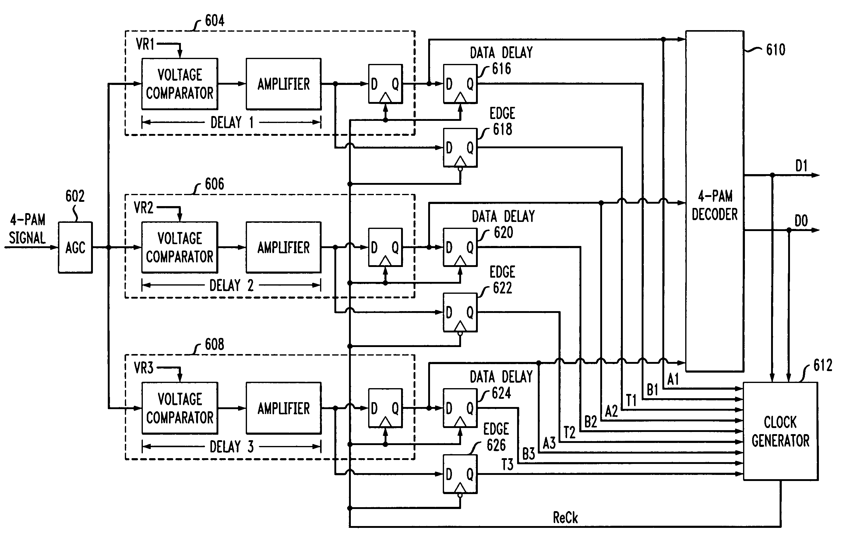
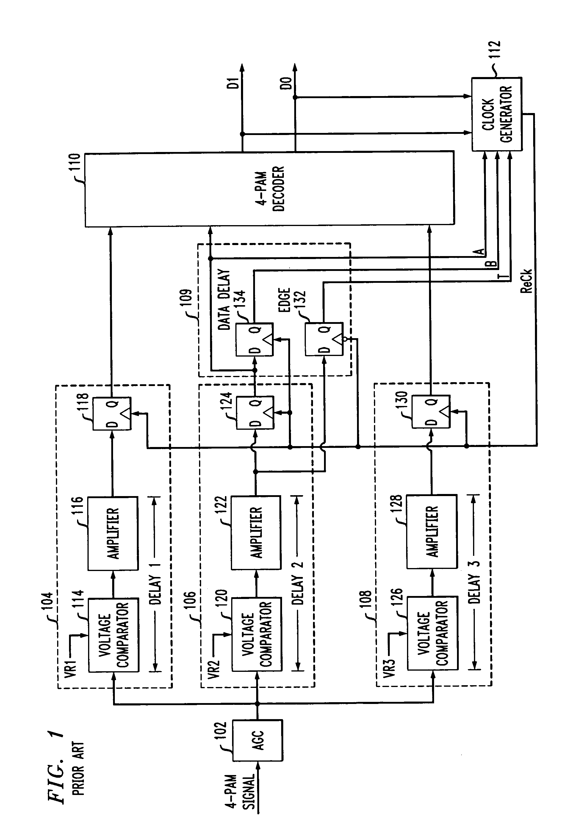
[0031]FIG. 1 is a block diagram of a 4-level pulse amplitude modulation (4-PAM) receiver of the prior art. It includes a data recovery circuit comprising automatic gain controller 102, slicers 104, 106, and 108, and 4-PAM decoder 110. It also includes a local clock recovery circuit that includes data delay and edge D-FFs 109, and clock generator 112.

[0032]Data Recovery Circuit

[0033]At the input to the receiver, a 4-PAM input signal is first gain adjusted by automatic gain controller 102 before being split three ...


PUM


Abstract

Multiple-level phase amplitude (M-PAM) clock and data recovery circuitry uses information from multiple phase detectors to generate one or more data sampling clocks that are optimized for each of the data slicers. One possible 4-PAM implementation includes 3 data slicers, 3 edge slicers, 3 phase detectors, and a single VCO. The phase detector outputs are combined (e.g., via weighted voting, weighted average, minimum error, and/or minimum variance) to determine an optimized phase estimate for the clock used to sample the data at all three data slicers. Another 4-PAM implementation similarly includes 3 data slicers, 3 edge slicers, 3 phase detectors, and a single VCO. The mid-amplitude edge slicer and phase detector are used in combination with the VCO to generate a central phase while a multiple-tap delay line provides N phase variants before and after the central phase. Information from the non-mid-amplitude edge slicers and phase detectors is used to choose a phase from among the phase variants that best suits the other data slicers. In yet another implementation, a single edge slicer, single phase detector, and single VCO is used to generate a key clock which is used by the edge slicer to track the symbol timing. A clock generator provides a single optimized clock (that is offset from the key clock) that is used by the data slicers. Bit error rates from the data slicers are used to adjust the offset until the data slicer clock is optimized with respect to all the slicers. Alternatively, multiple clocks are generated via offsets from the key clock, each being optimized to the data slicer group that it drives.

Description

BACKGROUND OF THE INVENTION[0001]1. Field of the Invention[0002]The present invention relates to clock and data recovery systems and, more specifically, to M-level pulse amplitude modulation (M-PAM) receivers.[0003]2. Description of the Related Art[0004]M-level pulse amplitude modulation (M-PAM) is a modulation technique that can be employed to reduce bandwidth requirements in data communication systems. Generally, an M-PAM transmitter modulates a carrier with one of M different amplitude levels per symbol, allowing log2M bits of data to be transmitted per symbol interval. 4-PAM is a subset of M-PAM where a carrier is modulated with one of 4 different amplitude levels per symbol, allowing 2 bits of data to be transmitted per symbol interval. 2-PAM corresponds to the common bi-level or binary modulation scheme.[0005]Data recovery of a transmitted M-PAM signal at a receiver is typically achieved using M−1 data slicers, an edge slicer, a phase detector, and a clock recovery circuit. A ...

Claims


Application Information

Patent Timeline
IPC IPC(8): H04L25/34H04L25/49H03L7/087H03L7/089H03L7/091H04L7/033H04L25/06
CPCH03L7/087H03L7/0891H03L7/091H04L25/4917H04L25/066H04L25/069H04L7/033
Inventor YANG, FUJICRANER, MICHAEL L.
Owner AVAGO TECH WIRELESS IP SINGAPORE PTE
Why Eureka
Try Eureka