Digital transmitter

a digital transmitter and transmitter technology, applied in the field of digital transmitters, can solve the problems that the system cannot scale to very high data rate binary or multi-level systems, and achieve the effect of substantial attenuation

Inactive Publication Date: 2006-08-29
THE UNIV OF NORTH CAROLINA AT CHAPEL HILL +1
View PDF22 Cites 62 Cited by
  • Summary
  • Abstract
  • Description
  • Claims
  • Application Information

AI Technical Summary

Benefits of technology

[0005]Conventional approaches to dealing with frequency dependent attenuation on transmission lines have been based on equalization, either in the transmitter or the receiver. For example, Tomlinson preceding is used in modems, and digital equalization in binary communication channels has been suggested in U.S. Pat. No. 4,374,426 to Burlage et al. However, such systems cannot scale to very high data rate binary or multilevel systems having bandwidths extending from near DC to greater than 100 MHz. Above 100 MHz, there is substantial attenuation due to skin effect resistance on conventional transmission lines.

Problems solved by technology

However, such systems cannot scale to very high data rate binary or multilevel systems having bandwidths extending from near DC to greater than 100 MHz.

Method used


Image

  • Digital transmitter
  • Digital transmitter
  • Digital transmitter

Examples


Embodiment Construction

[0025]A description of preferred embodiments of the invention follows.

[0026]The density and speed of modem VLSI technology can be applied to overcome the I / O bottleneck they have created by building sophisticated I / O circuitry that compensates for the characteristics of the physical interconnect and cancels dominant sources of timing and voltage noise. Such optimized I / O circuitry is capable of achieving I / O rates an order of magnitude higher than those commonly used today while operating at lower power levels.

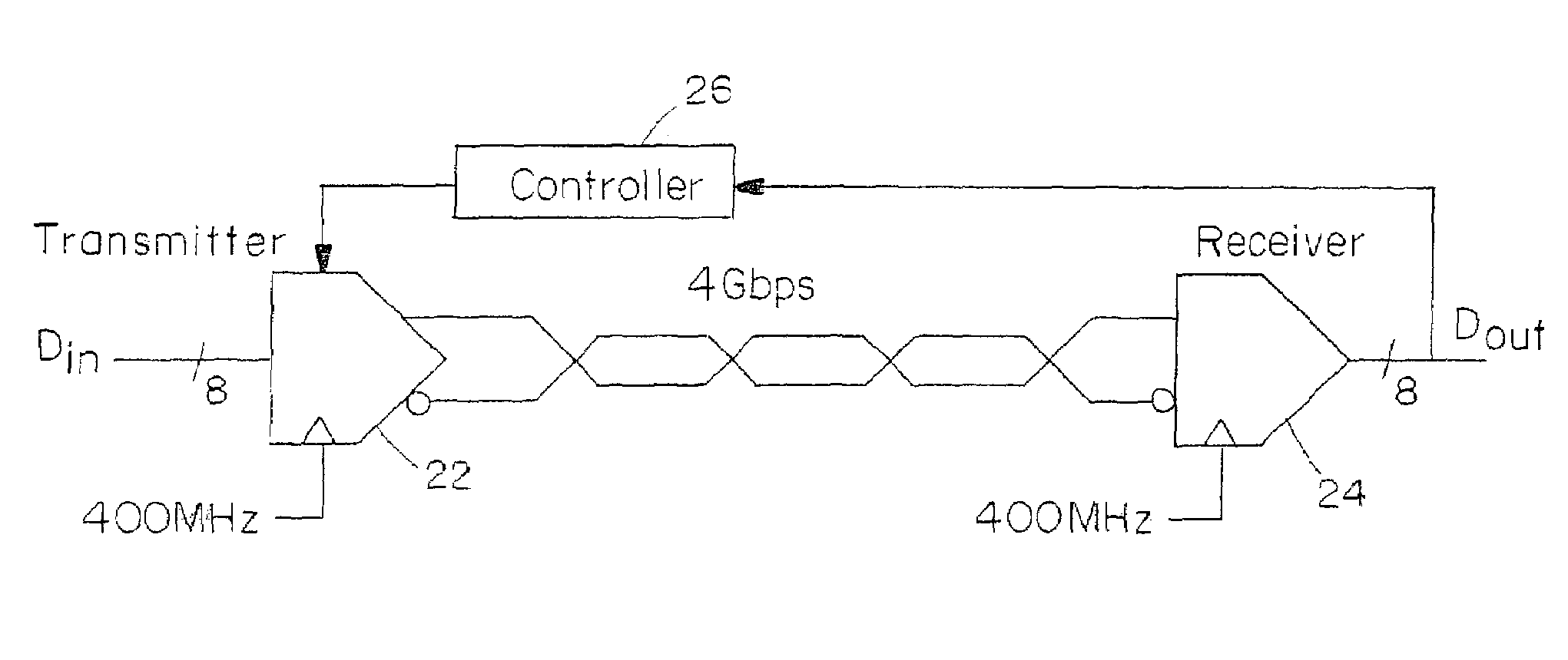
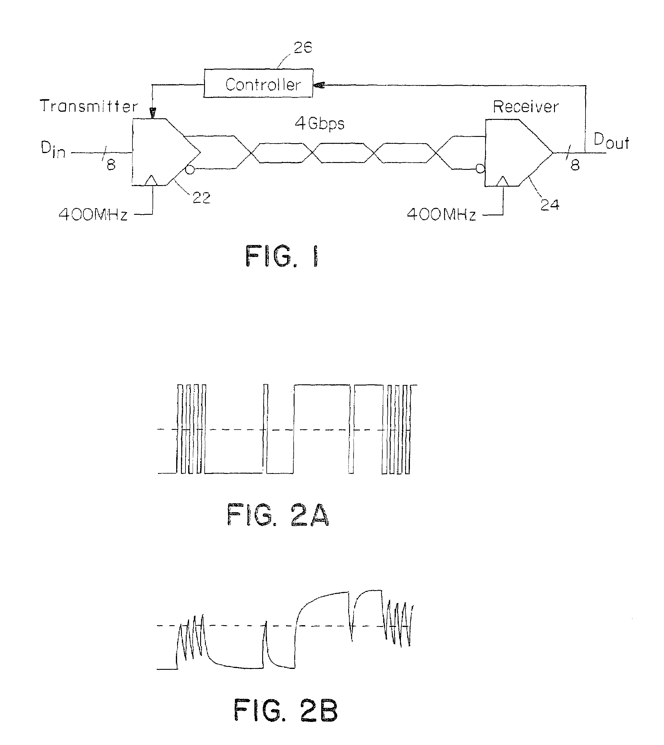
[0027]A system embodying the invention can achieve a four Gbps signaling rate using 0.5 μm CMOS circuits by controlling and compensating for characteristics of the transmission medium, by cancelling timing skew, and through careful management of time and voltage noise.

[0028]FIG. 1 shows one channel of high-speed signaling system embodying the invention. A transmitter module 22 accepts 8-bit parallel data at 400 MHz. Each byte is coded into 10 bits for band-limiting and forward...


PUM


Abstract

An equalizer provided in a digital transmitter compensates for attenuation in a signal channel to a digital receiver. The equalizer generates signal levels as a logical function of bit history to emphasize transition signal levels relative to repeated signal levels. The preferred equalizer includes an FIR transition filter using a look-up table. Parallel circuits including FIR filters and digital-to-analog converters provide a high speed equalizer with lower speed circuitry. The equalizer is particularly suited to in-cabinet and local area network transmissions where feedback circuitry facilitates adaptive training of the equalizer.

Description

RELATED APPLICATIONS[0001]This application is a continuation of application Ser. No. 09 / 852,481, filed on May 10, 2001, now U.S. Pat. No. 6,542,555, which is a continuation of Ser. No. 08 / 882,252, filed on Jun. 25, 1997, now U.S. Pat. No. 6,266,379, which is a continuation-in-part of Ser. No. 08 / 880,980, filed on Jun. 23, 1997, now abandoned, which claims the benefit of U.S. Provisional Application No. 60 / 050,098, filed on Jun. 20, 1997.[0002]The entire teachings of the above applications are incorporated herein by reference.GOVERNMENT SUPPORT[0003]The invention was supported, in whole or in part, by a grant No. F19628-92-C0045 from Department of the Air Force. The Government has certain rights in the invention.BACKGROUND OF THE INVENTION[0004]The performance of many digital systems is limited by the interconnection bandwidth between chips, boards, and cabinets. As VLSI technology continues to scale, system bandwidth will become an even more significant bottleneck as the number of I...

Claims


Application Information

Patent Timeline
Patent Type & Authority Patents(United States)
IPC IPC(8): H04K1/02H03H7/30H04L25/03H04L27/00
CPCH04L25/03343H04L25/03878H04L27/01H04L1/0042H04B3/04H04B1/1081H04L25/03025H04L25/03885H04L25/0272H04L25/0282H04B1/0483H04B1/16H04L25/03019
Inventor DALLY, WILLIAM J.
Owner THE UNIV OF NORTH CAROLINA AT CHAPEL HILL
Why Eureka
Try Eureka