Common rail directly actuated fuel injection valve with a pressurized hydraulic transmission device and a method of operating same

a technology of hydraulic transmission device and common rail, which is applied in the direction of valve operating means/release devices, electric control, machines/engines, etc., can solve the problems of increased likelihood of hydraulic displacement amplifier cavitation, inability to control the operation of the control valve, and increased likelihood of hydraulic displacement amplifier leakage into or out, so as to reduce the cost of directly actuating fuel injection valves, improve manufacturability, and add cost and complexity to the apparatus

Active Publication Date: 2006-09-05
WESTPORT FUEL SYST CANADA INC
View PDF32 Cites 14 Cited by
  • Summary
  • Abstract
  • Description
  • Claims
  • Application Information

AI Technical Summary

Benefits of technology

[0019]The pressure regulating device preferably comprises a displaceable member disposed between the fuel cavity and the reservoir. The displaceable member can be a piston movable within a cylinder with respective opposite ends of the piston associated with the fuel cavity and the reservoir. A seal can be provided between the piston and the cylinder. The seal can comprise at least one O-ring seal. The piston is movable to ensure that there is a low pressure differential across the seal, so that leakage is reduced and piston movement is generally slow. If the opposite ends of the piston have equal surface areas, then the piston will move to an equilibrium position at which the fluid pressure in the fuel cavity and the reservoir is equal. If, for example, the area of the piston end that is associated with the reservoir is smaller than the area that is associated with the fuel cavity, the piston will move to an equilibrium position at which the fluid pressure in the reservoir is greater than the fuel pressure in the fuel cavity. In this example, such a pressure gradient can help to prevent fuel from leaking into the reservoir and the transmission cavity, but the pressure gradient is preferably kept small to prevent excessive leakage of hydraulic fluid into the fuel cavity.
[0025]In another preferred embodiment, the plunger has an area transverse to its direction of movement that defines the volume that is displacable by movement of the plunger that is greater than an area of the valve member or the transmission member that is transverse to its respective direction of movement, and that defines the volume that is displacable by movement of the valve member or the transmission member. In this embodiment, because of the plunger has a larger end area than that of the valve member or transmission member, movement of the plunger results in a larger movement of the valve member, with the amplification ratio being proportional to the difference in areas.
[0064]Fuel injection valves can be operated without measuring needle position during an injection event using open loop control methods. That is, based upon command inputs such as desired load, and measured operating conditions, a command signal can be sent to the injection valve to lift the valve needle for each injection event. For this method, to achieve consistent operation, the fuel injection valve is designed with the objective of providing the same needle lift every time the same signal is sent to the injection valve actuator. A problem with open loop systems like this is that variables are introduced that influence needle position such as, for example, temperature effects, wear, fuel pressure, and combustion chamber pressure. It is more difficult and expensive to manufacture an injection valve that can mechanically compensate for the variable effects that can be encountered by a fuel injection valve during normal operation. For example, hydraulic compensators can be used to compensate for some variability in the dimensional relationship between the components of the fuel injection valve, but this adds cost and complexity to the apparatus. While it remains important for the valve member to respond in generally the same way for a given commanded signal, by employing the disclosed method of measuring the position of the valve member during an injection event, comparing it to the desired position to produce an error signal, and using the error signal to correct a commanded signal that a controller sends to the injection valve actuator, it is not important for the injection valve to be designed to respond in exactly the same manner when the same commanded signal is sent to the actuator. Rather, with the disclosed method, by design, there will be some variability of valve member position for a given commanded signal sent from the injection valve controller to the actuator because the method corrects the commanded signal to compensate for operational variables that influence needle member position. The closed loop feedback can be employed to make adjustments to the needle member position so that measured position closely approximates the desired position. Accordingly, the disclosed method can be used to improve manufacturability and to reduce costs of directly actuated fuel injection valves.

Problems solved by technology

A disadvantage of hydraulically actuated fuel injection valves is that it is not possible to control the operation of the control valve to move and hold the fuel injection valve needle to an intermediate position between the closed position and the fully open position.
A disadvantage with this arrangement is that there is a greater likelihood of cavitation in the hydraulic displacement amplifier if the movement of the actuator causes the fluid pressure to drop below the fluid's vapor pressure.
Another disadvantage is an increased likelihood of leakage into or out from the hydraulic displacement amplifier if there are significant differential pressures across the seals that seal the hydraulic displacement amplifier.
However, thermal and wear effects may not be completely compensated for by such systems and the amplified movement of the injection valve needle may not track the movements of the actuator accurately.

Method used


Image

  • Common rail directly actuated fuel injection valve with a pressurized hydraulic transmission device and a method of operating same
  • Common rail directly actuated fuel injection valve with a pressurized hydraulic transmission device and a method of operating same
  • Common rail directly actuated fuel injection valve with a pressurized hydraulic transmission device and a method of operating same

Examples


Embodiment Construction

)

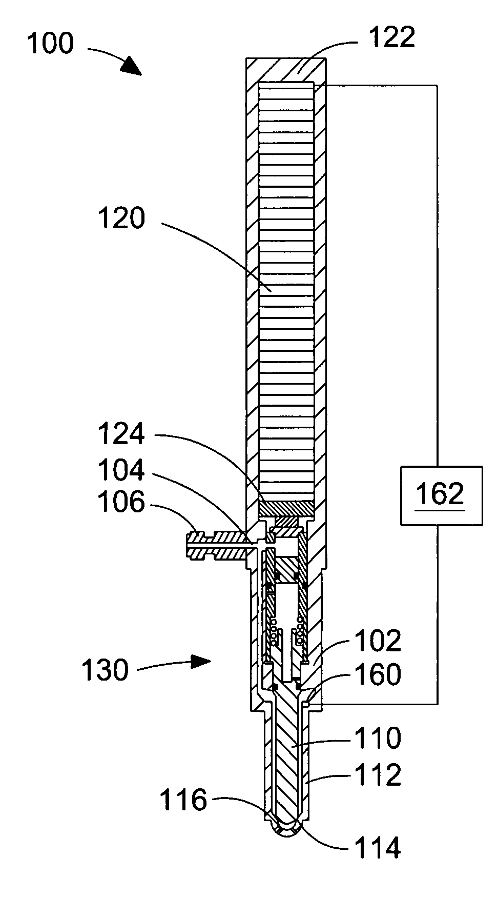
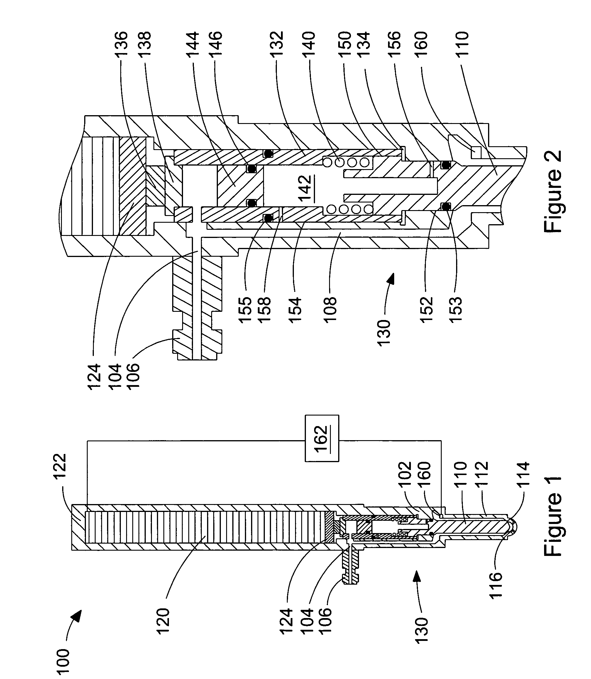
[0076]FIG. 1 and the enlarged view of FIG. 2 are schematic cross-sectional views of a preferred embodiment of a common rail directly actuated fuel injection valve. Fuel injection valve 100 is described in detail hereinafter with reference to FIGS. 1 and 2.

[0077]Valve body 102 can be formed by joining a plurality of pieces to facilitate the manufacturability of valve 100. Valve body 102 comprises a fuel inlet 104 through which fuel can be introduced into valve body 102. Coupling 106 is connectable to a fuel supply system (not shown) and provides an opening and a conduit through which fuel can be directed to fuel inlet 104.

[0078]As better shown in the enlarged view of FIG. 2, fuel cavity 108 is defined by valve body 102 and is in fluid communication with fuel inlet 104. In this embodiment, fuel cavity 108 comprises fuel passages through valve body 102 through which fuel can flow from fuel inlet 104 to an annular space around valve needle 110 provided within nozzle 112. Valve needle 1...


PUM


Abstract

A common rail directly actuated fuel injection valve is disclosed with a hydraulic transmission device that is fluidly isolated from the fuel so that the hydraulic fluid can be different from the fuel. This arrangement is particularly suitable for valves that inject a gaseous fuel, but can also be beneficial for use with liquid fuels. According to the method, the hydraulic fluid is pressurizable by the fuel pressure to reduce differential pressures and leakage, in addition to assisting with operation of the hydraulic transmission device. The method further comprises detecting the position of the valve needle for more accurate control of rate of fuel injection during an injection event.

Description

FIELD OF THE INVENTION[0001]The present invention relates to a common rail directly actuated fuel injection valve with a pressurized hydraulic transmission device and a method of operating such a fuel injection valve. More particularly, the disclosed fuel injection valve employs fuel pressure inside the fuel injection valve to pressurize a fluidly isolated hydraulic fluid, which can be a different fluid from the fuel, making this arrangement particularly suitable for injecting gaseous fuels.BACKGROUND OF THE INVENTION[0002]Modern diesel engines typically use a common rail fuel system that employs a fuel pump to supply diesel fuel at injection pressure to a plurality of fuel injection valves for injecting the fuel directly into each cylinder. That is, common rail fuel injection valves do not intensify fuel pressure inside the fuel injection valve. An advantage of common rail fuel systems is that fuel pressure and fuel injection events can be controlled independently of engine speed.[...

Claims


Application Information

Patent Timeline
Patent Type & Authority Patents(United States)
IPC IPC(8): F02M37/04F02M63/00B05B3/04F02D41/20F02M21/02F02M47/04F02M51/00F02M51/06F16K31/12
CPCF02D41/20F02D2200/063F02M51/0603F02M61/08F02M61/167F02M2200/24F02M2200/704F02M21/0263F02D19/024F02D19/027F02M21/0254Y02T10/30
Inventor MUMFORD, DAVIDANCIMER, RICHARDBAKER, MIKECLAPA, DAMIENWING, RICHARD
Owner WESTPORT FUEL SYST CANADA INC
Why Eureka
Try Eureka