Transparent article having protective silicon nitride film

a silicon nitride film and transparent article technology, applied in the field of transparent coatings, can solve the problems of thin transparent metal films of silver, copper and the like, prone to corrosion, physical marring of film stacks, etc., and achieve the effect of excellent resistance to corrosion

a silicon nitride film and transparent article technology, applied in the field of transparent coatings, can solve the problems of thin transparent metal films of silver, copper and the like, prone to corrosion, physical marring of film stacks, etc., and achieve the effect of excellent resistance to corrosion

US7101810B2Inactive Publication Date: 2006-09-05CARDINAL CG CO

Image

  • Transparent article having protective silicon nitride film
  • Transparent article having protective silicon nitride film

Examples


Embodiment Construction

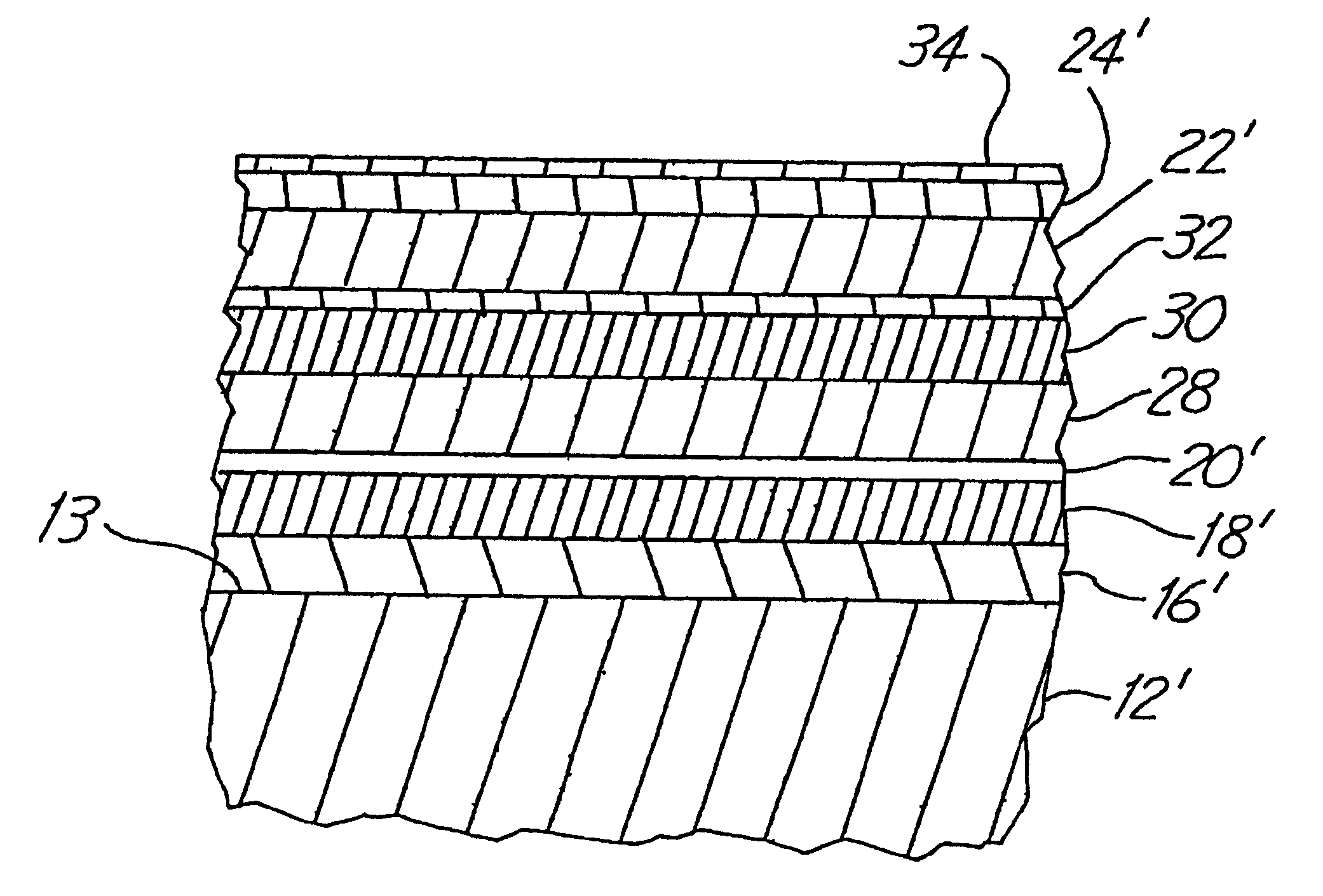
[0015]Referring first to FIG. 1, a transparent article 10 is shown as comprising a glass sheet 12 bearing a film stack 14. The film stack 14 may be manufactured by any convenient method, but magnetron sputtering techniques of the type described in U.S. Pat. No. 4,166,018, the teachings of which are incorporated herein by reference, are preferred. In this method, the glass sheet 12 is transported through a series of low pressure zones in which the various films which make up the film stack 14 are sequentially applied. Metallic films are sputtered from metallic sources or ā€œtargetsā€. Metal oxide or metal nitride films may be formed by sputtering the metal in a reactive oxygen or nitrogen atmosphere, or by first sputtering the metal on a substrate to form a film and then subjecting the metal film to a reactive atmosphere of oxygen or nitrogen. If desired, two or more contiguous films of different metal oxides may be used instead of a single metal oxide film. Magnetron sputtering techniq...


PUM

PropertyMeasurementUnit
temperatureaaaaaaaaaa
visible transmittanceaaaaaaaaaa

Abstract

Transparent articles comprising transparent, nonmetallic substrate and a transparent film stack is sputter deposited on the substrate. The film stack is characterized by including at least one infrared reflective metal film, a dielectric film over the metal film, and a protective silicon nitride film of 10 ā„« to 150 ā„« in thickness over the said dielectric film. The dielectric film desirably has substantially the same index of refraction as does silicon nitride and is contiguous with the silicon nitride film.

Description

RELATED APPLICATIONS[0001]This is a divisional of application Ser. No. 10 / 724,485, filed Nov. 28, 2003, now U.S. Pat. No. 6,942,917 which in turn is a continuation application of application Ser. No. 09 / 189,284, filed Nov. 10, 1998, now U.S. Pat. No. 6,673,438, which in turn is a divisional of application Ser. No. 08 / 547,690 filed Oct. 19, 1995, now U.S. Pat. No. 5,834,103, which in turn is a continuation of application Ser. No. 08 / 237,931 filed May 3, 1994, now abandoned all of which are incorporated by reference herein.FIELD OF THE INVENTION[0002]This invention is directed to transparent coatings for substrates and particularly to transparent coatings that are physically and chemically resistant.BACKGROUND OF THE INVENTION[0003]Glass and similar transparent substrates can be coated with transparent films to alter the optical properties of the glass. High visible transmittance, low emissivity coatings are characterized by their ability to transmit visible light while minimizing the...

Claims


Application Information

Patent Timeline
05 Sep 2006
Publication
US7101810B2
IPC
H01L21/469; B05D5/06; C03C17/36; G02B1/10; G02B5/20
CPC
C03C17/36; C03C17/3618; C03C17/3626; C03C17/3639; C03C17/3642; C03C17/3644; C03C17/3652; C03C17/366
Inventors
BOND, ROBERT; STANEK, ROGER P.