Rotor of a synchronous induction electric motor

a synchronous induction electric motor and synchronous induction technology, applied in the direction of positive displacement liquid engine, magnetic circuit rotating parts, magnetic circuit shape/form/construction, etc., can solve the problems of output falling, efficiency decreasing, and difficulty in providing holes in slit parts, so as to increase the magnetic resistance and efficiency.

Inactive Publication Date: 2006-09-05
MITSUBISHI ELECTRIC CORP
View PDF51 Cites 17 Cited by
  • Summary
  • Abstract
  • Description
  • Claims
  • Application Information

AI Technical Summary

Benefits of technology

[0007]It is an object of the present invention to provide a rotor of a synchronous induction electric motor which has less possibility of increasing magnetic resistance to cause an output fall and efficiency decrease when a gas vent hole is provided in the rotor in order to use the synchronous induction electric motor for a sealed type compressor.
[0008]Furthermore, it is another object of the present invention to provide a gas vent hole in a rotor which can be applied to other electric motors as well as the synchronous induction electric motor and by which oil contained in refrigerant gas can be separated and amount of oil circulation in a refrigerant circuit can be reduced.
[0009]Moreover, it is another object of the present invention to provide an electric motor, a sealed type compressor, a refrigerator or an air conditioner which has high efficiency and is inexpensive by way of utilizing the rotor of the synchronous induction electric motor and the gas vent hole of the rotor above-mentioned.

Problems solved by technology

However, since the slit formed in the rotor is filled up with aluminum, it is difficult to provide a hole in the slit part.
Furthermore, since the portion without the slit is a place where magnetic bundle passes, if a hole is shaped in such a portion, there will be a problem of increasing magnetic resistance to cause an output fall and efficiency decrease.

Method used


Image

  • Rotor of a synchronous induction electric motor
  • Rotor of a synchronous induction electric motor
  • Rotor of a synchronous induction electric motor

Examples


embodiment 1

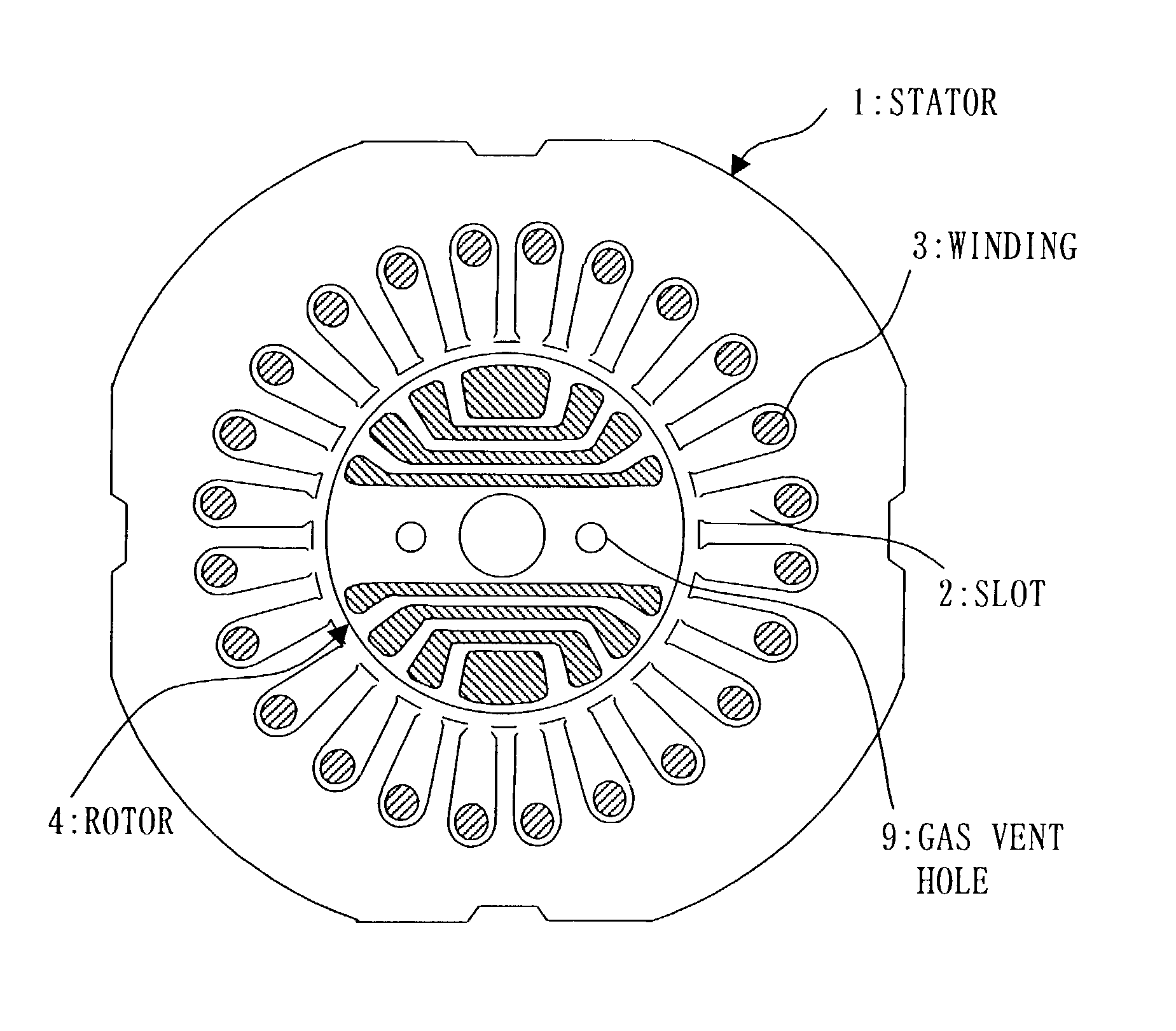
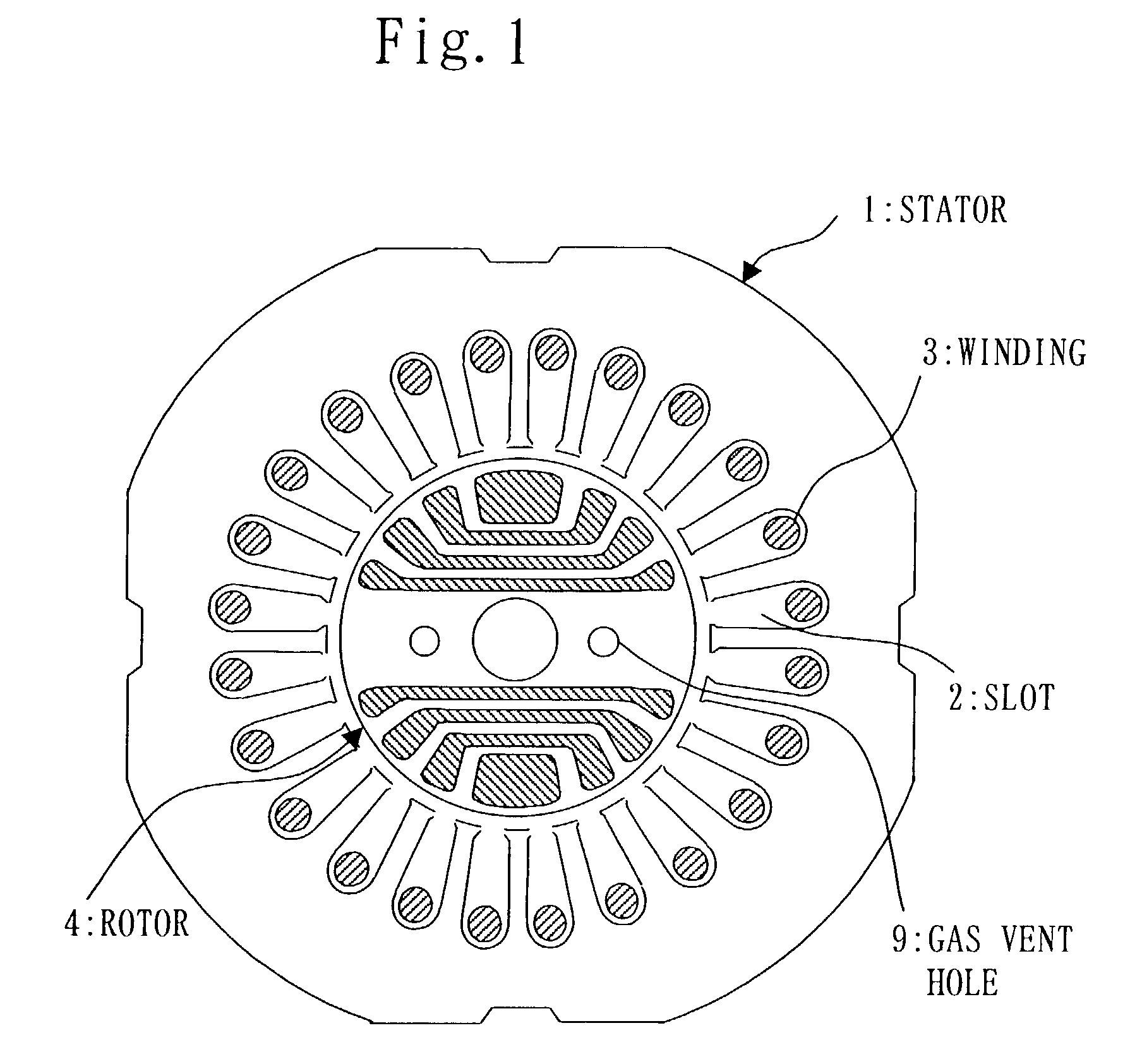
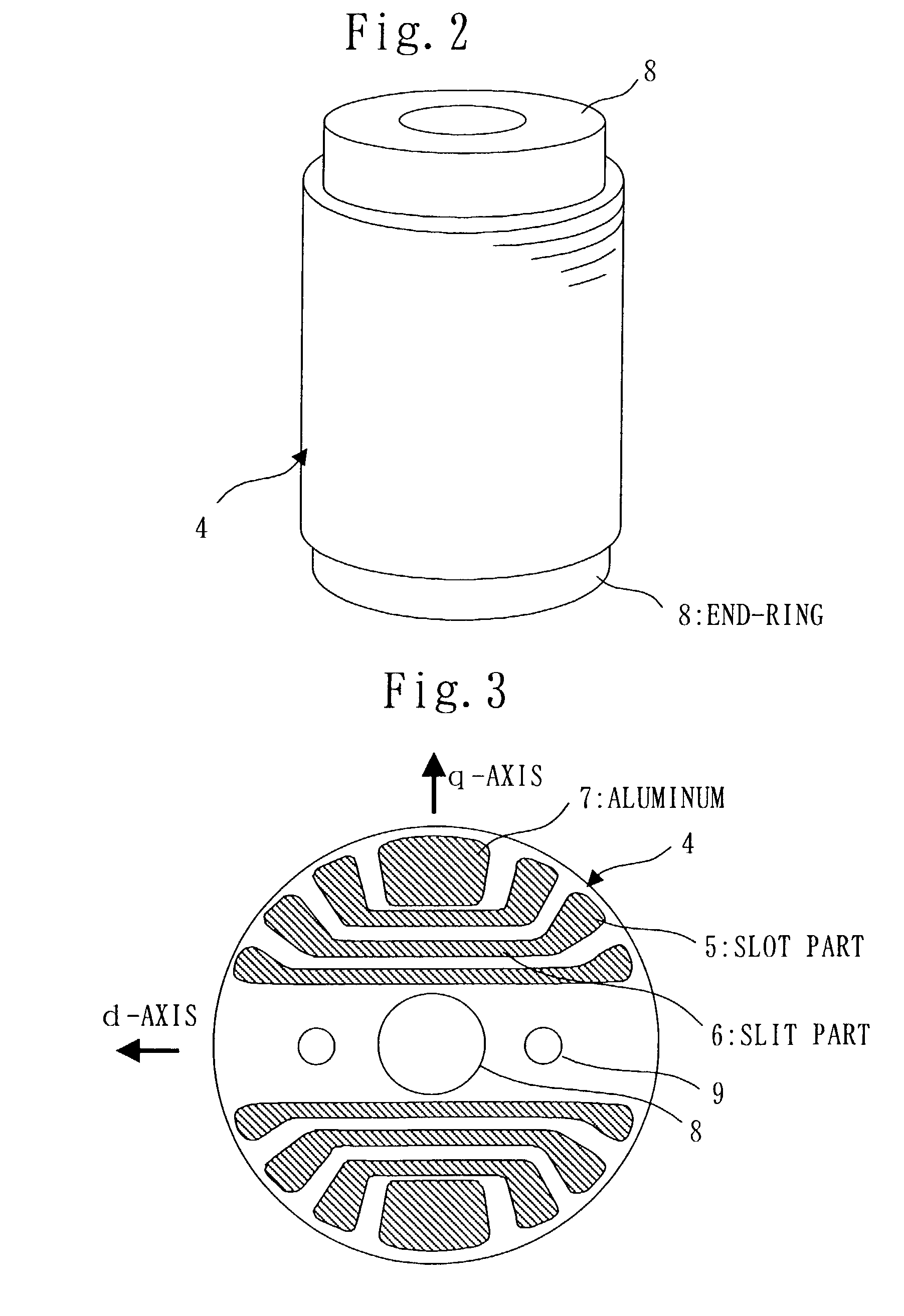
[0030]FIGS. 1 through 4 illustrate Embodiment 1. FIG. 1 shows a transverse sectional view of a stator and a rotor of a synchronous induction electric motor, FIG. 2 shows a perspective view of the rotor of the synchronous induction electric motor, FIG. 3 shows a transverse sectional view of the rotor of the synchronous induction electric motor, and FIG. 4 shows a transverse sectional view of the rotor of the synchronous induction electric motor where a non-filling part is formed at a slit.

[0031]In FIGS. 1 through 3, a stator 1 of the synchronous induction electric motor, a plurality of slots 2 provided at the inner circumferential side of the stator 1, windings 3, and a rotor 4 are provided. The winding 3 is wound at each of the plurality of slots 2 in order to generate magnetic flux for rotating the rotor 4. The rotor 4 is located inside the stator 1 and includes a slot part 5 for generating induction torque and a slit part 6 for generating reluctance torque. The slot part 5 and the...

embodiment 2

[0040]FIG. 5 shows a transverse sectional view of a rotor of a synchronous induction electric motor according to Embodiment 2. As shown in FIG. 5, the non-filling part 10 is provided in the slit part 6 which is the closest to the center of the rotor 4.

[0041]As structured above, the amount of aluminum of the end-ring 8 which functions as a rotor of the induction electric motor is not reduced. Therefore, it is possible to make secondary resistance of the rotor small and torque which is as an induction electric motor at a small slide area large. Accordingly, the operation led to synchronous operation from motor starting can be stably performed.

[0042]Moreover, when the synchronous induction electric motor is used for the sealed type compressor, rotation velocity of the non-filling part 10, which functions as a gas vent hole, becomes slow in the case of the non-filling part 10 being located close to the center of the rotor. Therefore, it is possible to reduce pressure loss of refrigerant...

embodiment 3

[0044]FIG. 6 shows a transverse sectional view of a rotor of a synchronous induction electric motor according to Embodiment 3. As shown in FIG. 6, two gas vent holes 9 in the shape of an oval are provided in the direction of the d-axis and in the radial direction, and each of the gas vent holes is in the shape of an oval and a long hole along the d-axis direction and the radial direction.

[0045]By dint of the structure described above, the increase of magnetic resistance in the direction of the d-axis at the portion which contributes to the reluctance torque generated by providing the gas vent hole 9 can be suppressed as much as possible. Then, the decrease of the inductance Ld in the direction of the d-axis generated by using the windings in the stator can also be suppressed as much as possible. Consequently, the reluctance torque becomes large, which makes the synchronous induction electric motor efficient. Moreover, since the torque can be large by a rotor whose height of the roto...


PUM


Abstract

A rotor of a synchronous induction electric motor according to the present invention includes a slot for generating induction torque and a slit for generating reluctance torque. The slot and the slit are filled up with aluminum which is short-circuited by an end-ring at each of both ends of the rotor, and the slit includes a non-filling part penetrating in the direction of the rotational axis and not filled up with the aluminum.

Description

BACKGROUND OF THE INVENTION[0001]1. Field of the Invention[0002]The present invention relates to a structure of a gas vent hole formed in a rotor of a synchronous induction electric motor which is started by mainly utilizing induction torque and in which a synchronous operation is performed by utilizing reluctance torque. The synchronous induction electric motor is used for a sealed type compressor etc.[0003]2. Description of Related Art[0004]As described in the document such as Utility Model Gazette No. 64-36581, a gas vent hole is provided in a rotor of an electric motor used for a sealed type compressor in order to enhance the efficiency of the sealed type compressor and reduce a pressure loss by way of making refrigerant gas pass better. In this case, the type of the electric motor is an induction electric motor, or a brushless DC motor in which a permanent magnet is used for the rotor.[0005]Also, as described in Utility Model Gazette No. 64-36581, an oil shielding board is prov...

Claims


Application Information

Patent Timeline
Patent Type & Authority Patents(United States)
IPC IPC(8): H02K1/26H02K1/22H02K19/02F04B39/00H02K1/32H02K15/00H02K15/02H02K17/16H02K19/06H02K19/10H02K29/00
CPCH02K1/246H02K17/165H02K15/0012H02K1/32H02K1/22
Inventor KAWAGUCHI, HITOSHITAKITA, YOSHIOYOSHINO, HAYATO
Owner MITSUBISHI ELECTRIC CORP
Why Eureka
Try Eureka