Information processing system has clock lines which are electrically isolated from another clock line electrically connected to clock buffer and termination voltage

a technology of information processing system and clock buffer, which is applied in the field of information processing system, can solve the problems of deterioration of clock signal with higher operation frequency, increased noise source on channel, and reduced amplitude of clock signal cfm, so as to prevent undesirable discrepancies in operation timing and reduce clock signal deterioration

Active Publication Date: 2006-09-05
SAMSUNG ELECTRONICS CO LTD
View PDF17 Cites 75 Cited by
  • Summary
  • Abstract
  • Description
  • Claims
  • Application Information

AI Technical Summary

Benefits of technology

[0011]It is another object of the present invention to provide an information processing system that prevents undesirable discrepancies of operational timings between data signals and clock signals regardless of the distance between memory devices and a chipset (or a memory controller).
[0012]It is yet another object of the present invention to provide an information processing system that reduces deterioration of clock signals to be transferred into devices, regardless of the distances involved.

Problems solved by technology

Unfortunately, using the serial bus architecture, the clock signal deteriorates with the higher operation frequency because the clock line 20 and the data bus 18 are not the same length.
As shown in FIG. 2, the amplitude of clock signal CFM is diminished and becomes more susceptible to noise sources on the channel.
Accordingly, as the distance between devices and the chipset increases, the jittering of the clock signal CFM increases correspondingly, causing discrepancies between timings of data input and output.
This is because long distance the clock signal must travel causes it to arrive at the memory device with an invalid signal level due to signal degradation.

Method used


Image

  • Information processing system has clock lines which are electrically isolated from another clock line electrically connected to clock buffer and termination voltage
  • Information processing system has clock lines which are electrically isolated from another clock line electrically connected to clock buffer and termination voltage
  • Information processing system has clock lines which are electrically isolated from another clock line electrically connected to clock buffer and termination voltage

Examples


Embodiment Construction

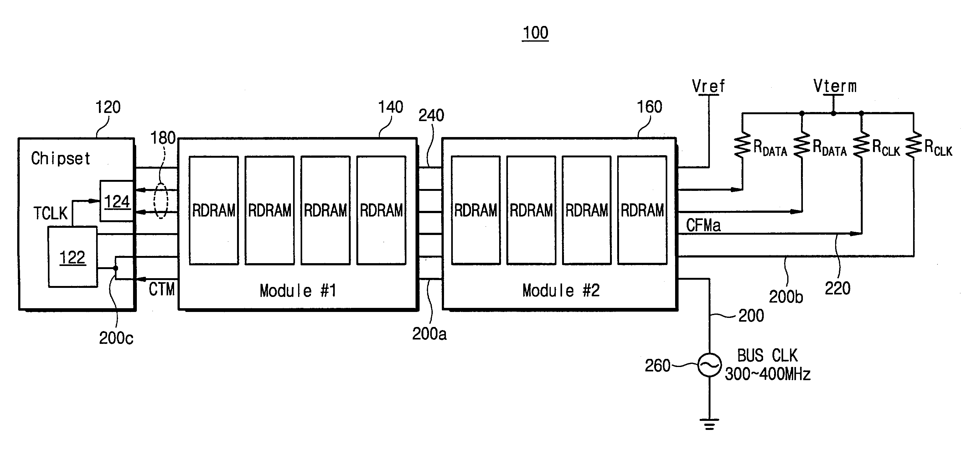
[0027]It should be understood that the following descriptions of preferred embodiments is merely illustrative and should not be taken in a limiting sense. In the following detailed description, specific details are set forth to provide a more thorough understanding of the present invention. It will be obvious to one skilled in the art, however, that the principles of the present invention may be practiced in many other ways. Practical embodiments of the invention will now be explained in conjunction with the drawings. FIGS. 3 through 6 illustrate one embodiment of an information processing system according to the principles of the present invention, while FIGS. 7 through 9 illustrate other potential embodiments according to the principles of the present invention.

[0028]Referring to FIG. 3, an information processing system 100 includes a chipset (or a memory controller) 120 and first and second memory modules (i.e., RIMMs) 140, 160. The chipset 120 and the memory modules 140, 160 are...


PUM


Abstract

A system includes modules, a clock generator that generates a first clock signal that is applied to the modules, and a chipset that controls the modules, the chipset having a clock buffer that generates a second clock signal. The system includes a first clock line that transfer the first clock signal to the clock buffer, the first clock line connected between the clock generator and a first termination circuit. The system includes a second clock line that transfer the second clock signal to the modules, the second clock line electrically isolated from the first clock line, the second clock line connected between the clock buffer and a second termination circuit.

Description

[0001]This application relies for priority upon Korean Patent Application No. 2002-2308, filed on Jan. 15, 2002, the contents of which are herein incorporated by reference in their entirety.BACKGROUND OF THE INVENTION[0002]1. Field of the Invention[0003]The present invention relates generally to an information processing system and, more specifically, to a digital information processing system employing memory modules constructed in serial bus architecture.[0004]2. Description of Related Art[0005]Referring to FIG. 1, a traditional information processing system 10 usually includes a chipset (or a memory controller) 12 and first and second Rambus in-line modules (RIMM) 14, 16, respectively. The chipset 12 and the memory modules 14, 16 are connected to a data bus 18 that includes a plurality of data lines, a clock line 20, and a reference voltage line 22. One end of the data bus 18 is connected to the chipset 12 while the other end is connected to a termination voltage Vterm (e.g., 1.8...

Claims


Application Information

Patent Timeline
Patent Type & Authority Patents(United States)
IPC IPC(8): G06F1/04G06F13/38G06F1/12G06F13/42
CPCG06F13/4243G06F13/38
Inventor MOON, BYONG-MO
Owner SAMSUNG ELECTRONICS CO LTD
Why Eureka
Try Eureka