Hot gas path assembly

a technology of hot gas path and assembly, which is applied in the direction of machines/engines, stators, liquid fuel engines, etc., can solve the problems of failure of the entire sealing arrangement, failure of cooling pressure, and no longer guaranteed

Inactive Publication Date: 2006-09-12
ANSALDO ENERGIA SWITZERLAND AG
View PDF18 Cites 20 Cited by
  • Summary
  • Abstract
  • Description
  • Claims
  • Application Information

AI Technical Summary

Benefits of technology

[0019]In an advantageous embodiment of the present device, furthermore, means for acting upon at least some of the segments by coolant independent of one another are provided. This may be implemented by means of a device that controls the supply of cooling medium to the individual segments via respective supply ducts independent of one another. In this way, an inhomogeneous temperature distribution can be compensated over the circumference of the flow duct during the operation of the turbomachine, in that individual segments are supplied with correspondingly adapted quantities of cooling medium. This is suitable, furthermore, for implementing a regulation of the gap width.

Problems solved by technology

One problem with a multiplicity of configurations is that, when, due to brushing, damage to the gas-permeable elements occurs or even a region is torn out completely, the coolant pressure collapses, and overheating and finally the failure of the entire sealing arrangement occur.
The cooling of the latter is no longer ensured, and local overheating occurs.
Due to the overheating, the region affected may burn up.
The component as a whole consequently fails over the entire circumference.
A further challenge that arises is to use the available cooling air as efficiently as possible, since, by virtue of a saving of cooling air, considerable power output and efficiency potentials can be exploited.

Method used


Image

  • Hot gas path assembly
  • Hot gas path assembly
  • Hot gas path assembly

Examples


Embodiment Construction

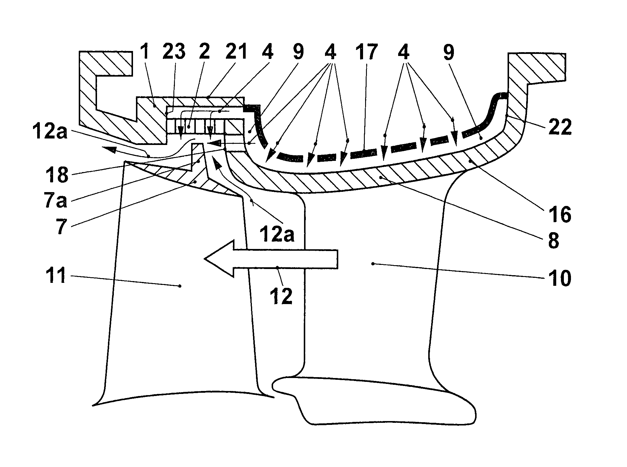
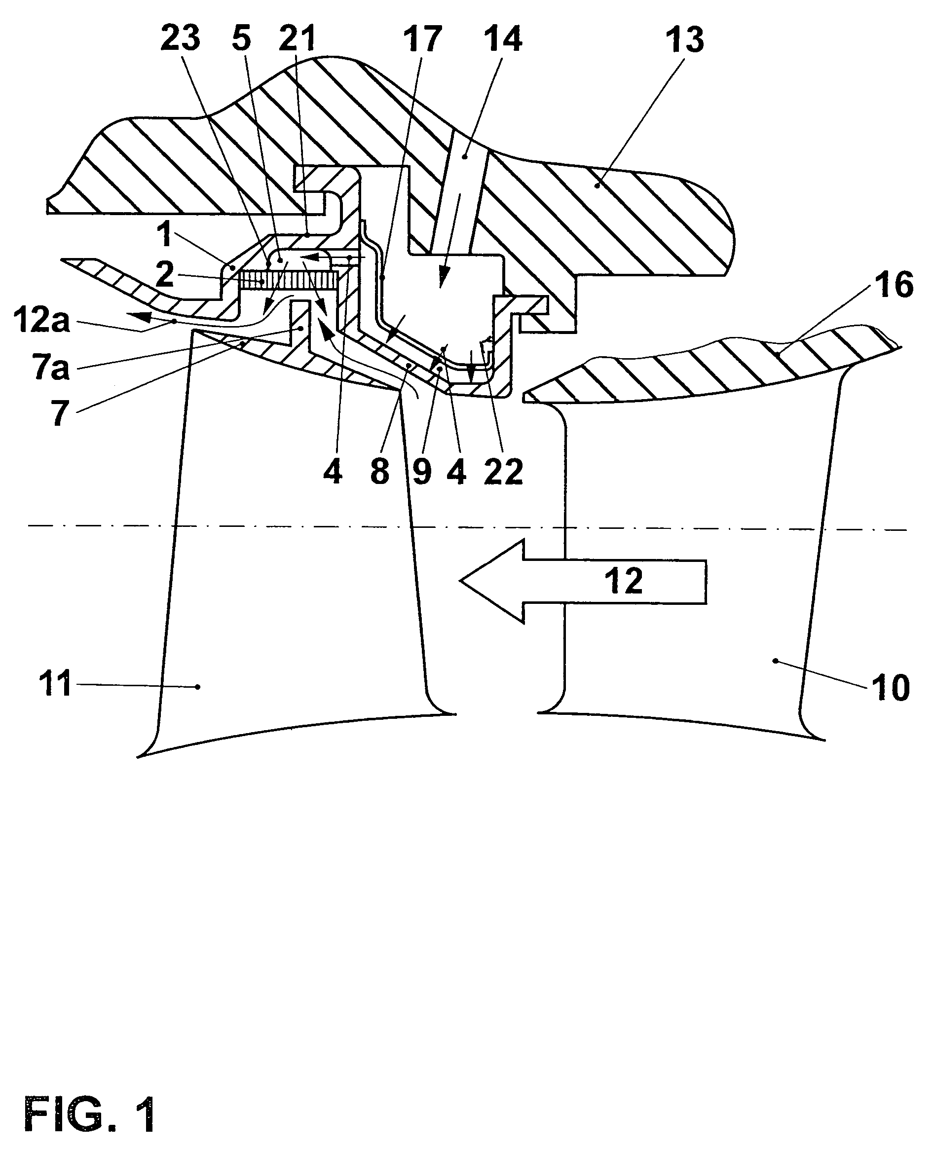
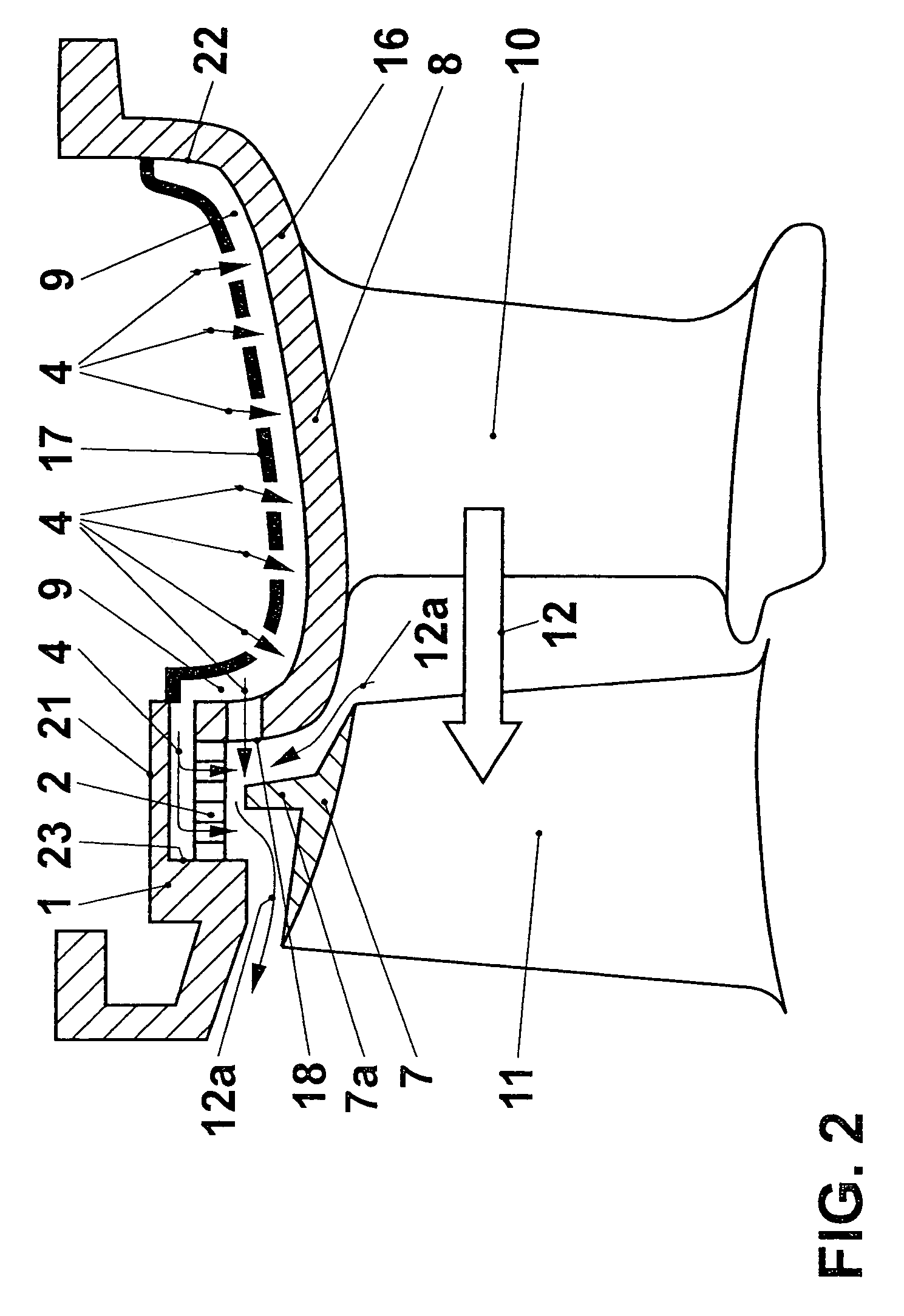
[0028]FIG. 1 shows a detail of a flow duct of a turbomachine, for example of a turbine of the gas turbo set. The hot gas flow 12 flows through the flow duct from right to left. A guide vane foot 16 with a guide vane 10 is arranged in the stator 13 in a way that is not illustrated and is not relevant to the invention, but is familiar to the person skilled in the art. A moving blade 11 with a cover band 7 and with cover band tips 7a is arranged downstream of the guide vane 10. The cover band tips, in conjunction with suitable stator elements 2 arranged opposite them, minimize the leakage gap and consequently the hot gas leakage flow 12a. Some of the leakage gap can be kept small under nominal conditions, the opposite element 2 is normally a comparatively soft brushing-tolerant element. This is designed in the present instance as a transpiration-cooled gas-permeable honeycomb element. The outflow for the coolant flowing through to flow out into the leakage gap in cross current to the l...


PUM

PropertyMeasurementUnit
distanceaaaaaaaaaa
gas-permeableaaaaaaaaaa
gas-impermeableaaaaaaaaaa

Abstract

A hot gas path assembly, suitable for use in the hot gas path of a gas turbine, has as a hot gas duct wall an impact-cooled gas-impermeable element and a transpiration-cooled gas permeable element. The gas-permeable element is a run-on covering for the sealing tip, and the gas-impermeable element is a blade foot of a turbine blade. Coolant is led in series through an impact-cooling element to cool the gas-impermeable element, and through the gas-permeable element for transpiration cooling and, if appropriate, also cools the sealing tip. Coolant thus is utilized particularly efficiently. Subdividing walls are arranged for the lateral subdivision of the coolant path, particularly in the circumferential direction, into segments. Because of the subdivision, in the event of damage to the gas-permeable element in one segment, the other segments remain essentially uninfluenced. Redundant cooling orifices may ensure coolant flow even when flow resistance in a transpiration-cooled element rises.

Description

CROSS-REFERENCE TO RELATED APPLICATIONS[0001]This application is a continuation of the U.S. National Stage designation of co-pending International Patent Application PCT / CH02 / 00686 filed Dec. 12, 2002, the entire content of which is expressly incorporated herein by reference thereto.FIELD OF THE INVENTION[0002]The present invention relates to a hot gas path assembly for a turbomachine, in particular for a gas turbine. It relates, furthermore, to a turbomachine in which an assembly according to the invention is used.BACKGROUND OF THE INVENTION[0003]The efficiency of an axial-throughflow gas turbine is influenced, inter alia, by leakage streams of the compressed gas that occur between rotating and nonrotating components of the turbine. The gap occurring between the tips of the moving blades and the casing walls surrounding the moving blades plays an appreciable part in this. Efforts are therefore aimed at keeping the gaps as small as possible. In the event of deviation from the design...

Claims


Application Information

Patent Timeline
Patent Type & Authority Patents(United States)
IPC IPC(8): F01D11/12F01D11/10F01D9/02F01D9/04F01D11/02F01D25/12F02C7/18
CPCF01D11/10F01D11/127F01D25/12F05D2300/612F05D2260/201
Inventor NAIK, SHAILENDRARATHMANN, ULRICH
Owner ANSALDO ENERGIA SWITZERLAND AG
Why Eureka
Try Eureka