Exposure system and method for manufacturing device

a manufacturing device and exposure system technology, applied in the field of exposure systems, can solve the problems of unstable gap between the fixed element (coil) and the cooling pipe, inability to control the temperature stability of the motor, and undetected effects of the stage operation performance, so as to prevent the occurrence of negative pressure, stabilize the performance of the exposure system, and increase the back pressure

Inactive Publication Date: 2006-09-12
NIKON CORP +1
View PDF22 Cites 11 Cited by
  • Summary
  • Abstract
  • Description
  • Claims
  • Application Information

AI Technical Summary

Benefits of technology

[0015]The present invention was made in consideration of the above problems. An object of the present invention is to provide an exposure system and a method for manufacturing a device by using the exposure system which can maintain a desirable performance by stabilizing a performance of the exposure system so as to improve an efficiency for manufacturing the device as a result by maintaining the cooling capacity by preventing the generation of the negative pressure in the circulation path for the liquid (cooling medium) and the increase of the back pressure even in a case in which at least a part of the temperature adjusting device is disposed under an installation surface of the exposure apparatus due to a limitation of the installation area.
[0017]According to the present invention, it is possible to prevent the generation of the negative pressure in the circulation path of the liquid even in a case in which at least a part of the temperature adjusting device is disposed under the installation surface on which the exposure apparatus is disposed because the tank which is disposed higher than the installation surface on which the exposure apparatus is disposed is connected to an intermediate section in a path which is directed from the object to the circulation device through the first piping arrangement; thus, a pressure of the liquid is applied to a vicinity of an upstream of the circulating device according to a height position of the tank.
[0020]According to the present invention, an airtight first tank is disposed in the path which is directed from the object to the circulating device under the installation surface on which the exposure apparatus is disposed, and a second tank is disposed higher than the installation surface on which the exposure apparatus is disposed such that the second tank and the first tank are connected through a first piping arrangement. In a case of such a structure, a great amount of negative pressure is generated because there is a great amount of vertical difference between the object and the first tank. The second tank which is disposed higher than the installation surface and the first tank which is disposed under the installation surface are connected through the first piping arrangement. Therefore, a great amount of pressure which corresponds to the vertical difference between the second tank and the first tank is applied on the tank (in the side of an upstream of the circulating device); thus, it is possible to prevent the generation of the negative pressure in the circulation path of the liquid similarly to a case of the exposure system according to the first aspect.
[0023]According to the present invention, a removing pipe is connected to the circulation path so as to remove the bubbles contained in the liquid. Therefore, if the circulating device performs a circulating operation for the liquid, the liquid which contains the bubbles and circulates in the circulation path flows into the pipe naturally; thus, the bubbles which are contained in the liquid are automatically removed merely by performing the circulating operation of the liquid. Such an operation is maintained during circulation of the liquid in the circulation path; therefore, it is possible to reduce the back pressure which is caused by the bubbles (ex. the air) which are contained in the liquid as time (number) for circulating the liquid goes by. Finally, it is possible to completely eliminate the back pressure which is caused by the air.
[0025]According to the present invention, a tank which is open to the atmosphere is provided. By doing this, it is possible to reduce the fluctuation of the surface of the liquid even if there is a fluctuation of volume which is caused by a pressure in the piping arrangement. As a result, it is possible to monitor the fluctuation of the surface of the liquid; thus, it is possible to improve the reliability without the liquid leaking.
[0027]In the above exposure system, it is possible to prevent occurrence of negative pressure and increase in back pressure in the circulation path of the liquid; thus, a cooling capacity is maintained so as to stabilize a performance of the exposure system at a desirable performance level. As a result, it is possible to improve an efficiency for manufacturing the devices.

Problems solved by technology

When this negative pressure is generated, a case may occur in which some kinds of deformation may occur in the cooling pipe (which forms a part of the circulation path) which is disposed in the reticle stage and the wafer stage as an object of which the temperature is supposed to be controlled; thus, there may be a concern that an operation performance of the stage will be undesirably affected.
As an example, in a case in which a cooling pipe is disposed in a linear motor (moving-magnet type) which drives the stage, if the cooling pipe is deformed by the negative pressure, a gap between the fixed element (coil) and the cooling pipe is unstable.
As a result, the fluid amount of the cooling medium which flows in the gap is unstable; thus, temperature stability is unstable in the motor.
Therefore, there are concerns that a stability of a thrust force of the motor may be unstable, or there may be a temperature distribution on a surface of the cooling pipe; thus, there is undesirable influence on accuracy for overlapping the baselines.
However, air cannot necessarily be removed from the highest point of the circulation path if this method is used; therefore, there may be a case in which it is not possible to eliminate air in the circulation path completely.
If air remains in the circulation path, a back pressure is generated in the circulation path; therefore, if a small pump is used which does not have a sufficient compressing capacity so as to resist the force of air which ascends upwardly, there is a concern that a cooling capacity for the stage may be reduced because it is no possible to flow a desirable fluid amount in the circulation path as a result.
; thus, there is a problem in that it is not possible to increase the fluid amount of the liquid when the back pressure increases in the circulation path.

Method used


Image

  • Exposure system and method for manufacturing device
  • Exposure system and method for manufacturing device
  • Exposure system and method for manufacturing device

Examples


Embodiment Construction

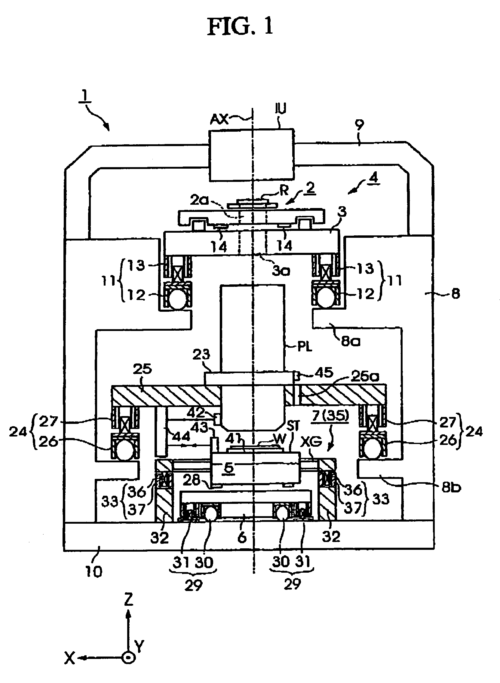
[0036]An exposure system and a method for manufacturing a device according to an embodiment of the present invention are explained with reference to drawings below. FIG. 1 is a view showing a general structure of an exposure system which is provided in an exposure apparatus according to a first embodiment of the present invention. The present embodiment is explained with reference to an example in which the present invention is applied to an exposure system according to a step and scan method which manufactures a semiconductor element by transferring a pattern which is formed on a reticle R onto a wafer W while moving the reticle R as a mask and the wafer W relative to an optical projection system PL.

[0037]Here, explanations are made as follows in which an XYZ orthogonal coordinate system which is shown in FIG. 1 is set so as to explain a positional relationship of each members with reference to this XYZ orthogonal coordinate system. In the XYZ orthogonal coordinate system, the X ax...


PUM

PropertyMeasurementUnit
temperatureaaaaaaaaaa

Abstract

An exposure system is provided which can maintain a predetermined performance of the exposure apparatus stably by maintaining a cooling capacity by preventing a negative pressure from being generated in a circulation path of the liquid and preventing the back pressure from increasing even if at least a part of a temperature adjusting device is disposed under a disposition surface of the exposure apparatus due to the disposition area. A sealed tank which stores the cooling agent which is circulated in the circuiting systems and a pump, etc., which circulates the cooling agent are disposed under the disposition surface FL of the exposure system. The reticle stage and the wafer stage which are objects of which the temperature is supposed to be controlled are disposed above the disposition surface FL. A tank which open to air is provided so as to prevent the negative pressure from being generated in the reticle stage, etc. such that the tank and the tank are connected by a connecting piping arrangement. Also, the piping arrangement which eliminates the bubbles which are contained in the cooling agent which is circulated in the circulating systems are connected to the circulating systems.

Description

[0001]This is a Continuation of International Application No. PCT / JP03 / 05283 filed Apr. 24, 2003. The entire disclosure of the prior application is hereby incorporated by reference herein in its entirety.BACKGROUND OF THE INVENTION[0002]1. Field of the Invention[0003]The present invention relates to an exposure system which transfers a pattern formed on a mask or a reticle onto a substrate such as a wafer, and to a method for manufacturing devices such as a semiconductor element, a liquid crystal displaying element, an image-capturing element, a thin film magnetic head, and other devices by using the exposure system.[0004]The present application is based on Patent Application No. 2002-122567, filed in Japan, the content of which is incorporated herein by reference.[0005]2. Description of Related Art[0006]An exposure apparatus which transfers a pattern which is formed on a mask or a reticle (hereinafter generally referred as a mask) onto a wafer or a glass plate, etc., on which a pho...

Claims


Application Information

Patent Timeline
Patent Type & Authority Patents(United States)
IPC IPC(8): G03B27/42G03B27/32G03B27/52G03F7/20
CPCG03F7/70858G03F7/70875G03F7/70991G03F7/709G03F7/70891
Inventor TSUJI, TOSHIHIKONAGAHASHI, YOSHITOMOFUJII, MANABUMURAKAMI, HIRONORI
Owner NIKON CORP
Why Eureka
Try Eureka