
Magnetic sensor with second antiferromagnetic layer having smaller depth in height direction than free layer

a technology of antiferromagnetic layer and magnetic sensor, which is applied in the field of magnetic sensors, can solve the problems of thermal fluctuation of free magnetic layer b>4/b>, disadvantageous reduction of reproduction sensitivity of free magnetic layer to an external magnetic field, and decrease of curie temperature, etc., and achieves suppressing the generation of side readings and improving reproduction sensitivity.

Inactive Publication Date: 2006-09-12
TDK CORPARATION
View PDF7 Cites 5 Cited by
  • Summary
  • Abstract
  • Description
  • Claims
  • Application Information

AI Technical Summary

Benefits of technology

[0022]Accordingly, the present invention was made to solve the current problems described above, and an object of the present invention is to provide a magnetic sensor and manufacturing method thereof, the magnetic sensor capable of improving the reproduction sensitivity by an exchange bias method even when the track width is decreased and of suppressing the generation of side reading.

Problems solved by technology

However, when the track width Tw is decreased in order to meet the trend toward a higher recording density, in the magnetic sensor shown in FIG. 20, the following problem has occurred.
However, as the track width is decreased, a region strongly influenced by the bias magnetic field described above is relatively increased in the central portion 4b, and as a result, the reproduction sensitivity of the free magnetic layer 4 to an external magnetic field is disadvantageously decreased.
In order to improve the reproduction sensitivity, the exchange stiffness constant of the free magnetic layer 4 may be decreased as described above; however, when the exchange stiffness constant is excessively decreased, the Curie temperature is decreased, and as a result, thermal fluctuation of magnetization of the free magnetic layer 4 becomes a problem.
As a result, the generation of Barkhausen noise or noise caused by ferromagnetic resonance induced by thermal fluctuation becomes serious.
However, when the exchange coupling magnetic field described above is decreased, the fixation of the magnetization of the side portion 4a is also decreased, and as a result, a problem of side reading may arise, which is generated by magnetization inversion in the side portion 4a caused by an external magnetic field.
However, when the film thickness of the free magnetic layer 4 is excessively decreased, a problem may arise in that the stability of reproduction waveforms is decreased or noise caused by thermal fluctuation is generated.

Method used


Image

  • Magnetic sensor with second antiferromagnetic layer having smaller depth in height direction than free layer
  • Magnetic sensor with second antiferromagnetic layer having smaller depth in height direction than free layer
  • Magnetic sensor with second antiferromagnetic layer having smaller depth in height direction than free layer

Examples


Embodiment Construction

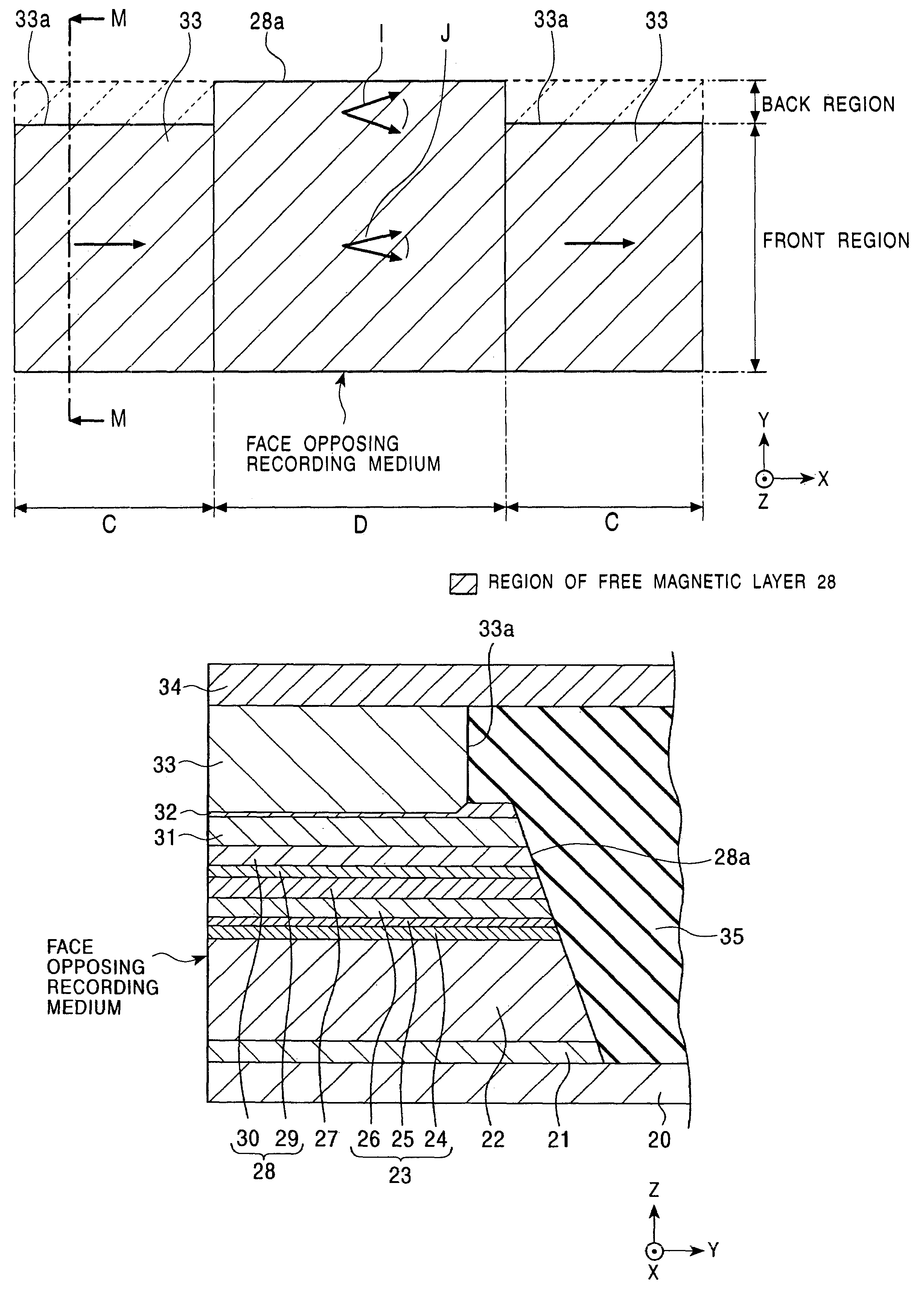
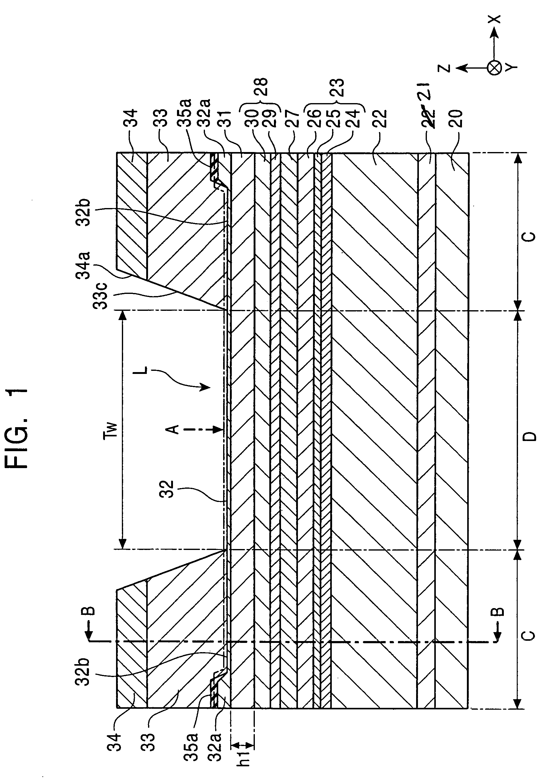
[0067]FIG. 1 is a partial cross-sectional view showing the structure of a magnetic sensor (spin-valve type thin film element) of the present invention, which is viewed from a face opposing a recording media.

[0068]Reference numeral 20 indicates a substrate. On the substrate 20, a seed layer 21 composed of a NiFe alloy, a NiFeCr alloy, or Cr is formed. The seed layer 21 is a film, for example, composed of 60 atomic percent of (Ni0.8Fe0.2) and 40 atomic percent of Cr and having a thickness of 60 Å.

[0069]On the seed layer 21, a first antiferromagnetic layer 22 is formed. The first antiferromagnetic layer 22 is formed of a PtMn alloy, an X—Mn alloy (where X is at least one element selected from the group consisting of Pd, Ir, Rh, Ru, Os, nickel (Ni), and iron (Fe)), or a Pt—Mn—X′ alloy (where X′ is at least one element selected from the group consisting of Pd, Ir, Rh, Ru, Au, Ag, Os, Cr, Ni, argon (Ar), neon (Ne), xenon (Xe), and krypton (Kr)).

[0070]As the first antiferromagnetic layer 2...


PUM

PropertyMeasurementUnit
Thicknessaaaaaaaaaa
Antiferromagnetismaaaaaaaaaa
Heightaaaaaaaaaa

Abstract

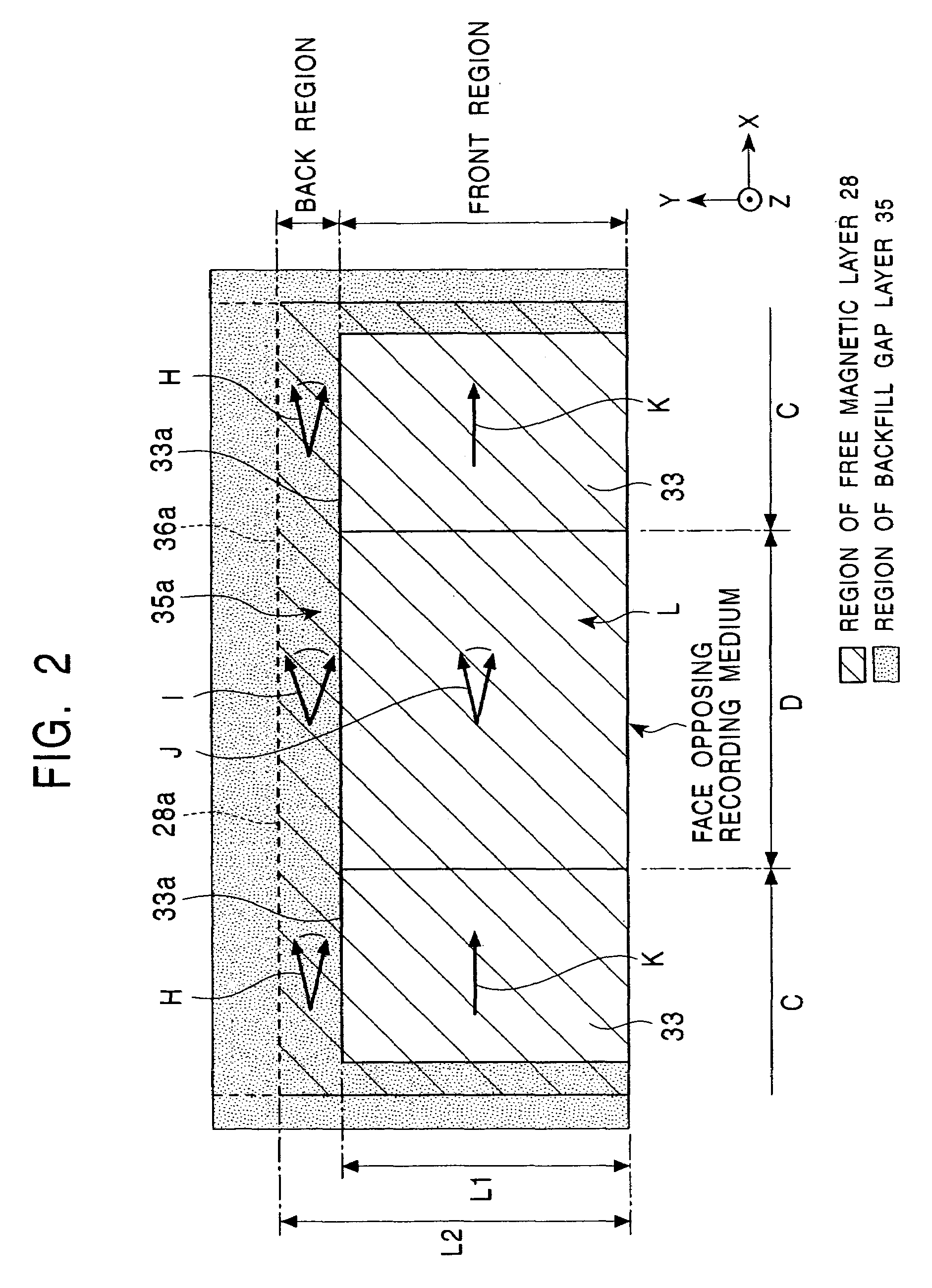
An end portion of a backfill gap layer is provided on two side portions of a free magnetic layer in a back region, and second antiferromagnetic layers are formed on the two side portions of the free magnetic layer from a face opposing a recording medium to the end portion of the backfill gap layer. Accordingly, in the free magnetic layer in the back region, a bias magnetic field in the magnetic layer is decreased as compared to that in the front region. Hence, a magnetic sensor can be manufactured which can improve the reproduction sensitivity of a central portion of the free magnetic layer to an external magnetic field as compared to that in the past without decreasing the exchange stiffness constant and which can suppress the generation of side reading.

Description

BACKGROUND OF THE INVENTION[0001]1. Field of the Invention[0002]The present invention primarily relates to magnetic sensors each performing magnetization control of a free magnetic layer by an exchange bias method, and more particularly, relates to a magnetic sensor and a manufacturing method thereof, the magnetic sensor capable of improving reproduction sensitivity even when a track width is decreased and of suppressing the generation of side reading.[0003]2. Description of the Related Art[0004]FIG. 20 is a partial cross-sectional view showing the structure of a conventional magnetic sensor, viewed from a face opposing a recording medium.[0005]Reference numeral 1 indicates a first antiferromagnetic layer, and on the antiferromagnetic layer 1, a fixed magnetic layer 2, a non-magnetic material layer 3, and a free magnetic layer 4 are formed in that order, thereby forming a multilayer film 7.[0006]In the magnetic sensor shown in FIG. 20, on two side portions 4a of the free magnetic la...

Claims


Application Information

Patent Timeline
IPC IPC(8): G11B5/39G01R33/09H01F10/32H01L43/08H01L43/12
CPCB82Y10/00B82Y25/00G01R33/093G11B5/3909G11B5/3903Y10T29/49046G11B5/3967G11B2005/3996
Inventor HASEGAWA, NAOYAUMETSU, EIJI
Owner TDK CORPARATION
Learn More