Apparatus for focusing plasmon waves

a technology of plasmon waves and apparatus, applied in the field of near field optics, can solve the problems of 25 nm diameter of heated surface and too small throughput to be practical for hamr

Inactive Publication Date: 2006-09-12
SEAGATE TECH LLC
View PDF18 Cites 31 Cited by
  • Summary
  • Abstract
  • Description
  • Claims
  • Application Information

AI Technical Summary

Benefits of technology

[0009]The present invention comprises apparatus that generates an intense, but very small, radiating source of light by efficiently converting an incident light beam into a surface plasmon wave, brin...

Problems solved by technology

One of the difficulties with the technique is finding a method to heat just the small area of media which is to be recorded.
Heating with laser light, as is done in magneto-optic recording, is the most promising approach, but the difficulty with this is ...

Method used


Image

  • Apparatus for focusing plasmon waves
  • Apparatus for focusing plasmon waves
  • Apparatus for focusing plasmon waves

Examples


Embodiment Construction

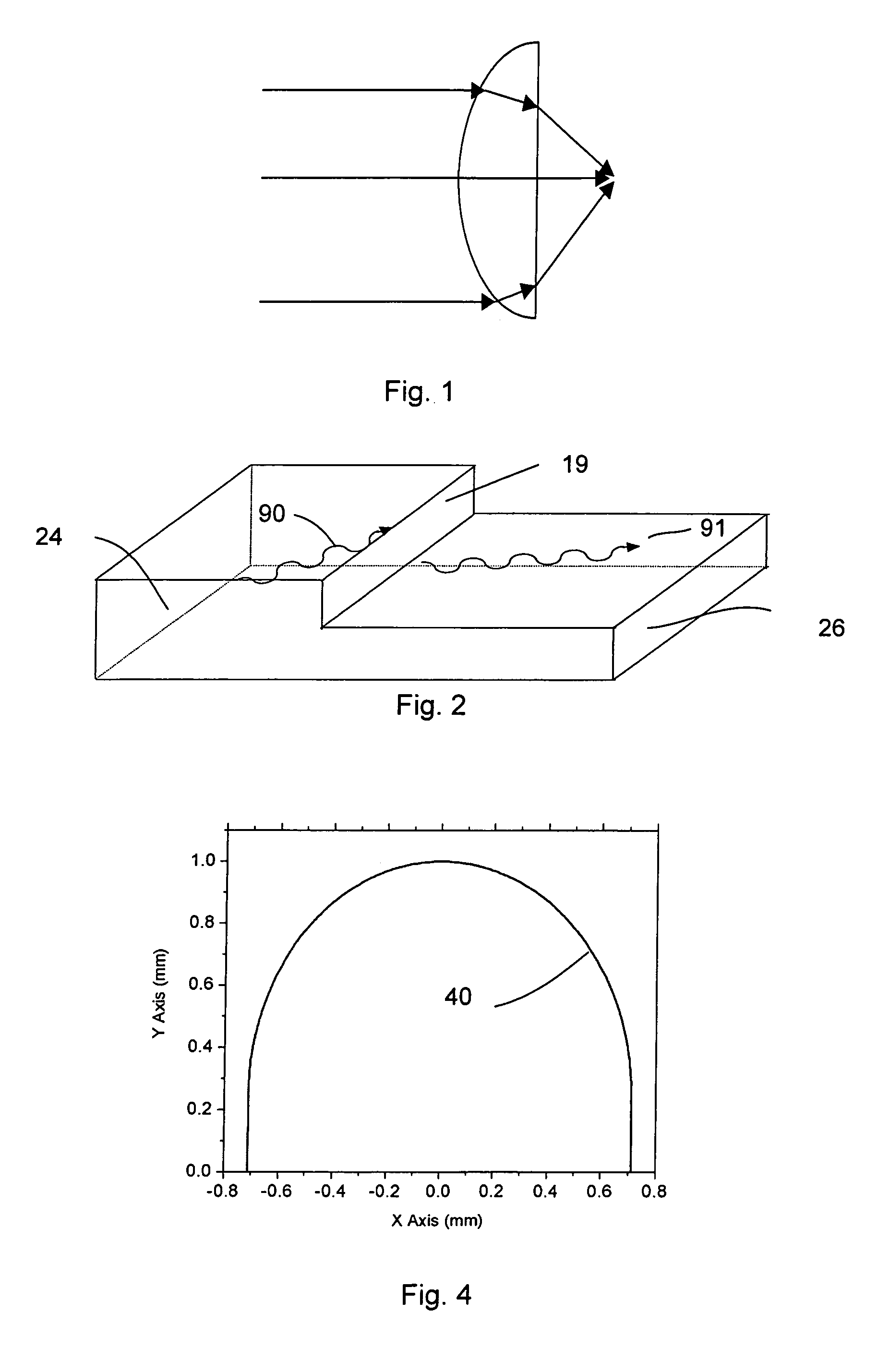
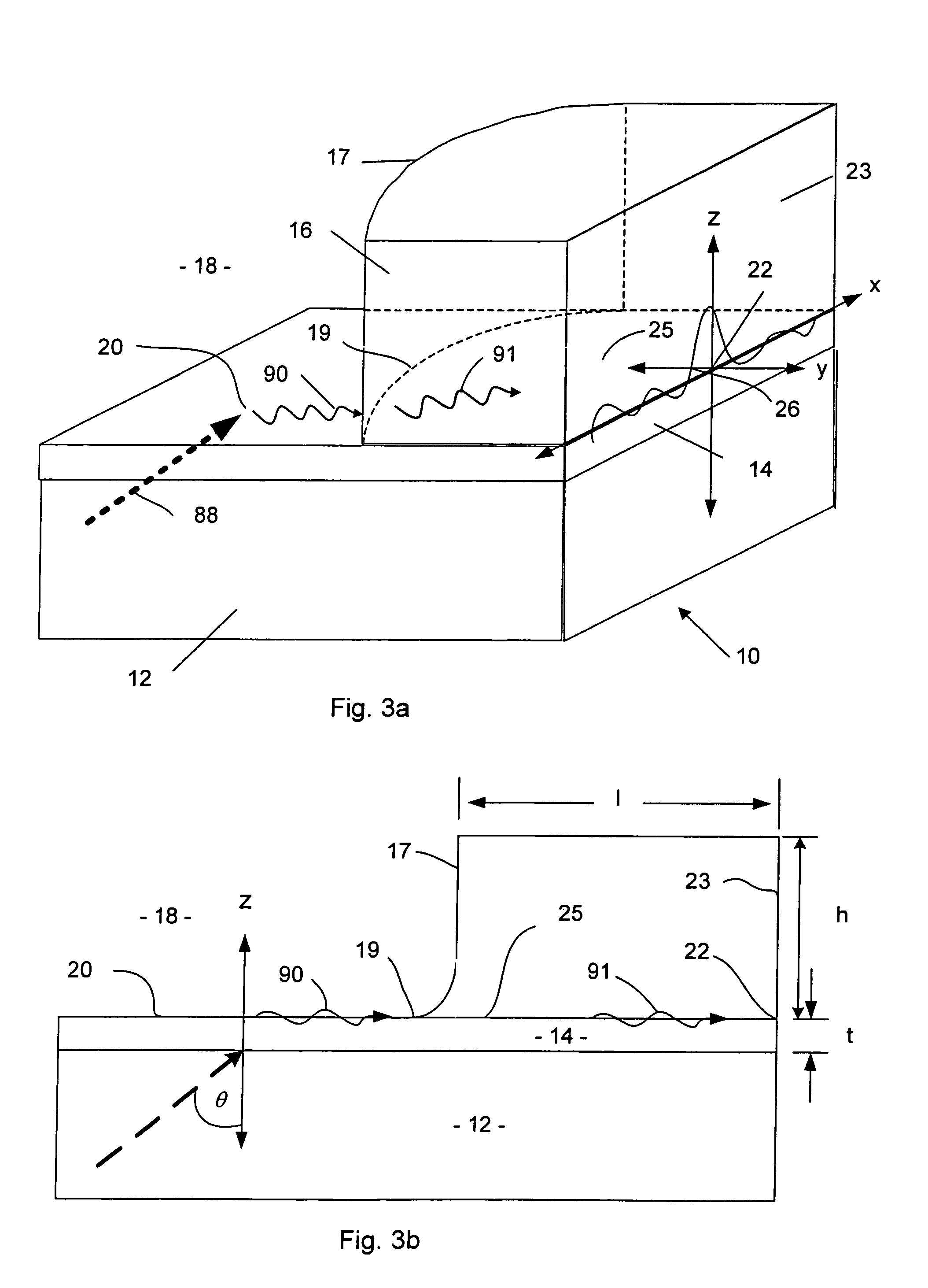
[0031]The Appendix describes the science of plasmon waves, in connection with FIGS. 1 and 2, and provides a theory of operation of present invention. The first embodiment of present invention is illustrated in FIGS. 3a and 3b.

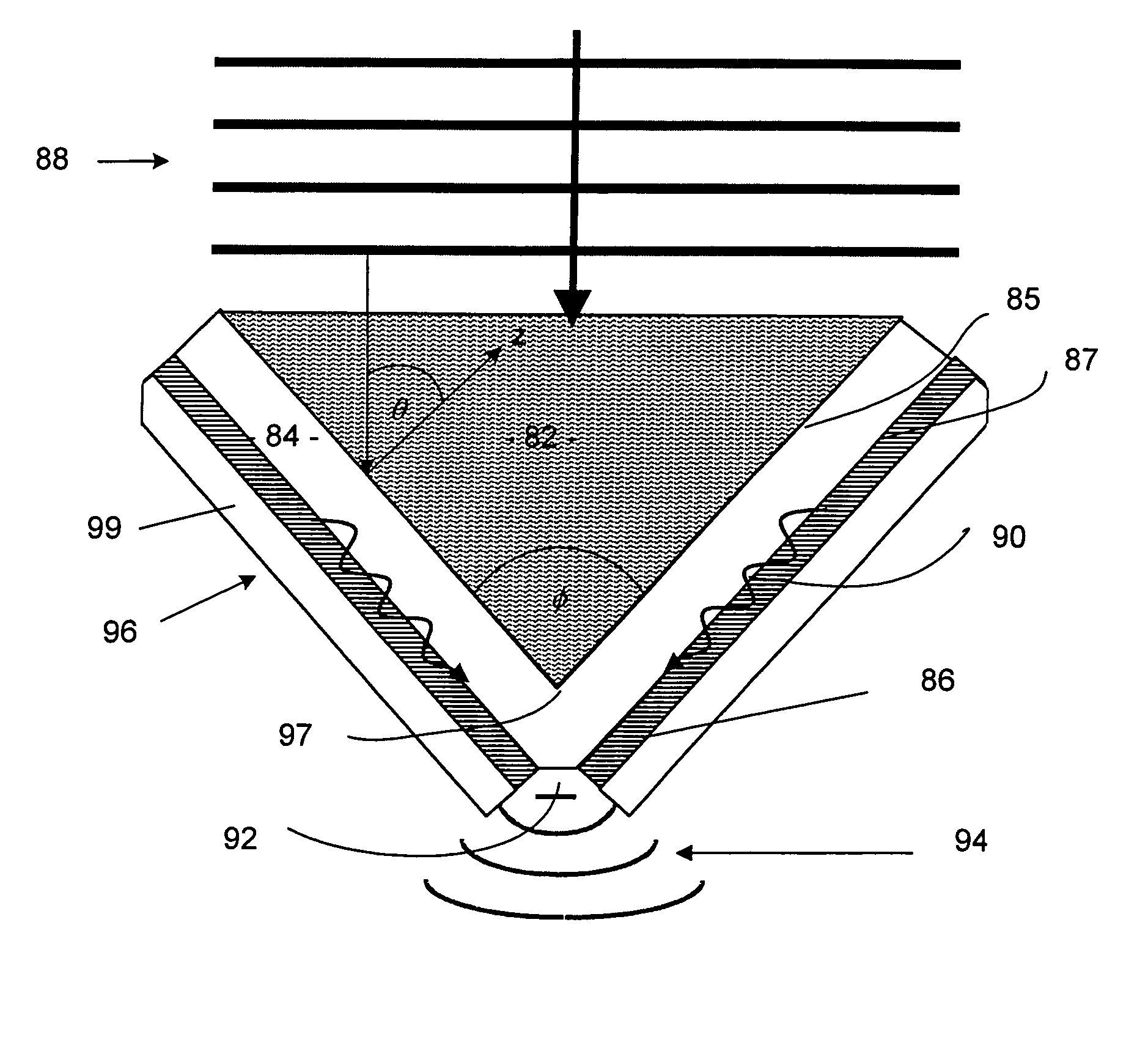
[0032]FIG. 3a is a perspective view of a plasmon lens 10 that converts incident light beam 88 into a plasmon wave 90, diffracts the waves at a lens surface 17 into a refracted plasmon wave 91 that is focused on a spot 22 located on the a flat surface 23 of the lens 10. At the flat surface 23, the plasmon wave 91 converts back into light, which may be used to observe a sample in a microscope application, or to heat the surface of a disc in a magnetic recording application.

[0033]The lens 10 structure consists of a pair of high index dielectric layers 12, 16 which may be made of SiO2, SiN, Ta2O5, ZnS, TiO2, Si or other high index materials known in the art sandwiching a thin (typically 14 which may be made of gold, silver, aluminum, or copper. The space 18 above ...


PUM


Abstract

An apparatus for focusing plasmon waves to a spot. The plasmon waves are there converted to light. In one application, the light is used for heat induced magnetic recording. In another application, the light is used as a part of near field scanning microscope. The plasmon waves may be induced on a converging rectangular cone having an aperture. The plasmon waves may also be focused on a flat surface by a curved dielectric lens. In the heat induced magnetic recording embodiment, a magnetic pole structure is integrated into the focusing apparatus, either as one surface of the rectangular cone, or as a layer upon which the curved dielectric lens is formed.

Description

CROSS-REFERENCE TO RELATED APPLICATIONS[0001]This application claims benefit of U.S. provisional patent application Ser. No. 60 / 346,378, filed on Jan. 7, 2002, 60 / 346,379, filed on Jan. 7, 2002, and 60 / 346,431, filed on Jan. 7, 2002, which are herein incorporated by reference.BACKGROUND OF THE INVENTION[0002]1. Field of the Invention[0003]The invention relates to the field of near field optics and more particularly to its use in heat assisted magnetic recording.[0004]2. Description of the Related Art[0005]Heat-assisted magnetic recording (HAMR) involves heating a spot on the disk surface to reduce its coercivity sufficiently so that it can be magnetically recorded. The advantage of this technique is that the coercivity of the media at ambient can be significantly increased, thereby improving thermal stability of the recorded data even for very small bit cells. One of the difficulties with the technique is finding a method to heat just the small area of media which is to be recorded....

Claims


Application Information

Patent Timeline
IPC IPC(8): G02B6/10G11B7/135G01Q60/18G01Q60/22G01Q80/00G02B6/122G02F1/1368G11B5/00G11B5/127G11B5/187G11B9/00G11B11/105
CPCB82Y20/00B82Y35/00G01Q60/22G02B6/1226G11B5/127G11B5/187G11B7/1387B82Y10/00G01Q80/00G11B2005/0021G11B9/1409G11B11/10534G11B2005/0005G02F1/1368
Inventor CHALLENER, WILLIAM ALBERT
Owner SEAGATE TECH LLC
Why Eureka
Try Eureka