
Computer readable magnetic resonance method calculating on-line gradients during imaging

a magnetic resonance and gradient technology, applied in the field of magnetic resonance imaging, can solve the problems of gradient echo methods, inefficient k-space sampling strategies of early pi methods, limited application of sodium mri in diagnostic radiology and clinical research, etc., and achieve good signal-to-noise ratio, good sampling of k-space, and easy imaging

Inactive Publication Date: 2006-09-19
THE UNIV OF QUEENSLAND
View PDF14 Cites 8 Cited by
  • Summary
  • Abstract
  • Description
  • Claims
  • Application Information

AI Technical Summary

Benefits of technology

[0006]By separating the variables describing the selected trajectory, in the coordinate system appropriate to the gradient coils, into variables which are constant from projection to projection and variables which change from projection to projection, the method and device in accordance with the invention allows a significant fraction of the variables to be calculated prior to imaging. These calculated values are then stored and used for realtime calculations of parameters which must be changed during the course of the imaging process as projections are stepped through. As a result of this separation of the variables into two groups as described, it is possible to significantly reduce the wave form memory requirements to a size which allows current gradient controllers to perform the required mathematic functions online.
[0008]In a particularly preferred application of the method and device, the trajectory selected is a substantially uniform sampling density, three-dimensional trajectory. This embodiment has the advantage, in particular in combination with the imaging of sodium nuclei, of providing a good sampling of k-space using a number of samples which is still small enough to facilitate imaging with good signal to noise ratio in a reasonable amount of scan time.
[0009]In a preferred embodiment of the invention, the selected trajectory is a three-dimensional twisted projection imaging sequence with extremely short echo times. This particular application has the advantage of providing efficient use of wave form memory requirements for the gradient controller with a scheme for sampling phase space leading to good signal to noise ratios for reasonable data set sizes.
[0010]In a preferred embodiment of the invention, the coordinate system in which the variables and functions for the selected trajectory are expressed is a Cartesian coordinate system. This particular embodiment has the advantage that most gradient systems used in imaging are gradient systems which generate a Cartesian coordinate gradient combination in x, y, and z directions. The Cartesian coordinate system for the selected trajectories is therefore the natural choice for expressing the functions required for the wave form generator of the corresponding gradient.
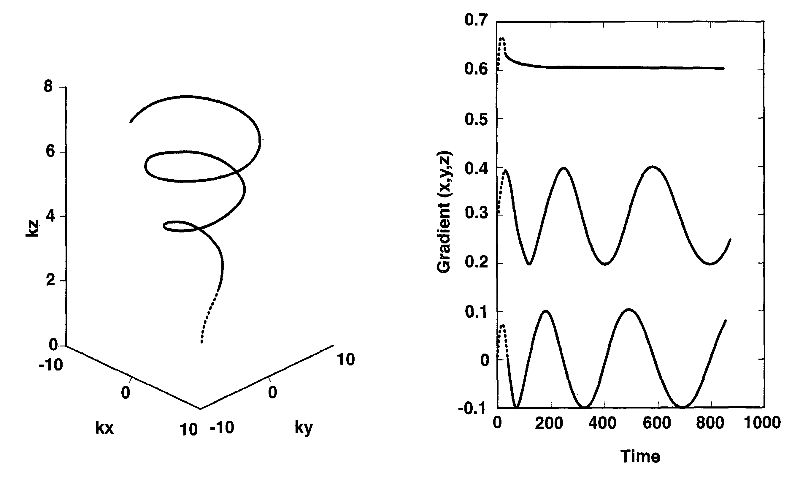
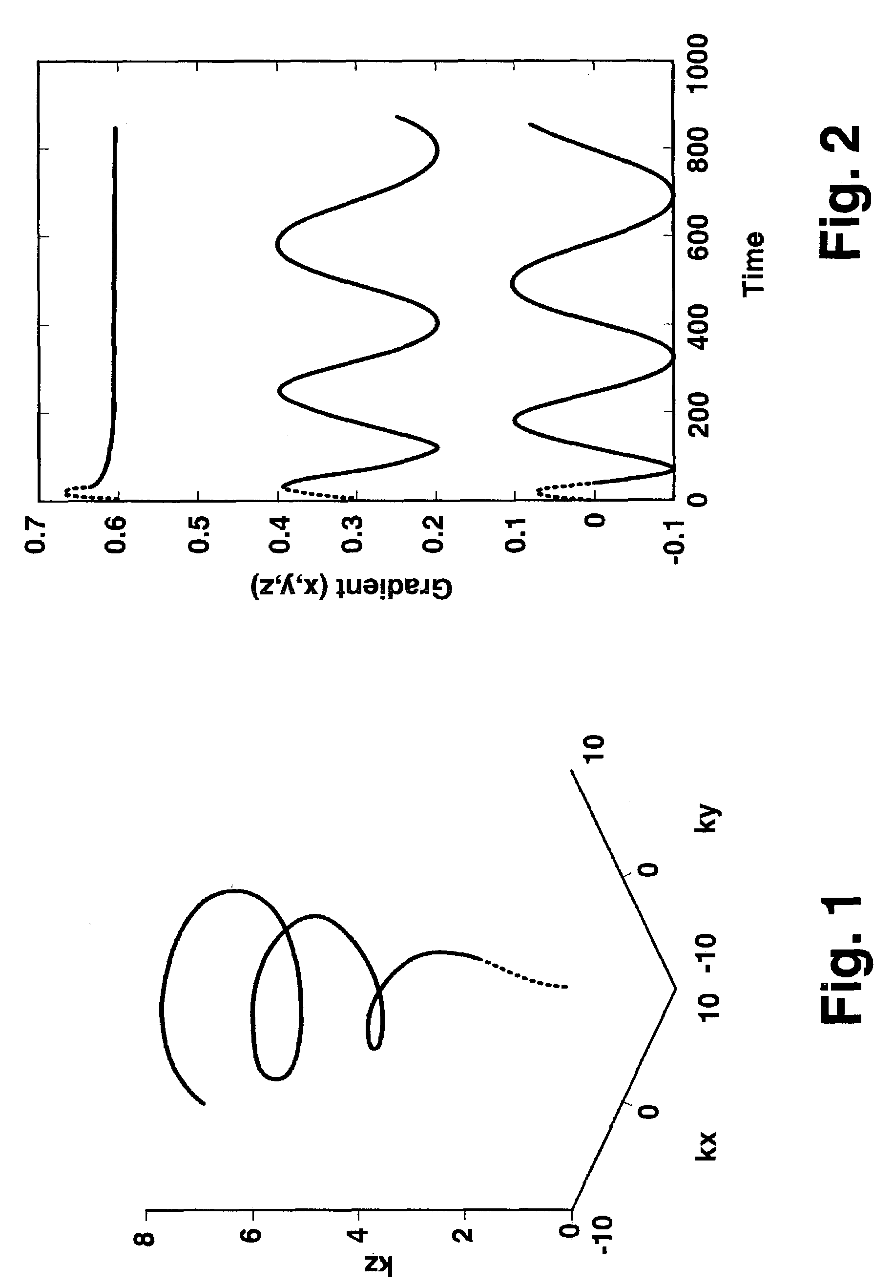
[0011]In a preferred embodiment of the invention, the selected trajectories are twisted spiral trajectories. This particular embodiment has the advantage of providing efficient k-space sampling with increased efficiency and has been shown capable of producing sodium imaging of diagnostic quality in reasonable amounts of imaging time and for reasonable size data sets.

Problems solved by technology

The application of sodium MRI in diagnostic radiology and clinical research has been limited due to the technical difficulty of imaging this quadrupolar nucleus.
Unfortunately, these early PI methods have suffered from inefficient k-space sampling strategies, and gradient echo methods from excessive T2 weighting.
Three-dimensional twisted projection-imaging (TPI) sequences with extremely short echo times (TE˜0.4 ms) have recently been shown to produce sodium images of diagnostic quality.9 This approach however does not utilize the potential of the scheme to minimize the noise variance of a sodium image through the uniform sampling of k-space.

Method used


Image

  • Computer readable magnetic resonance method calculating on-line gradients during imaging
  • Computer readable magnetic resonance method calculating on-line gradients during imaging
  • Computer readable magnetic resonance method calculating on-line gradients during imaging

Examples


Embodiment Construction

[0017]One solution to the mathematical condition that allows the constant sampling of k-space represent “twisted spiral” trajectories, similar (but not consistent with) those reported by Boada et al (1997).9 This solution can be expressed in polar coordinates by

[0018]ki=(3⁢⁢γ⁢⁢G⁢⁢k02⁢t+k03)1 / 3(1.1)ϕi=12⁢⁢sin⁢⁢θ0⁢(((ki / k0)4-1)-tan-1⁡((ki / k0)4-1))+ϕ0(1.2)

where k is the spatial frequency vector (equivalent to the radius of the trajectory), γ is the gyromagnetic ratio of the imaged nucleus (23Na), G is the maximum gradient strength, and φ and θ0 are the azimuthal and polar angles, respectively. k0 is the approximate position where the k-space trajectory evolves according to equations 1.1–1.2 and is given by

k0=2Δxp  (1.3)

where Δx and p denote the desired spatial resolution and trajectory twist, respectively.

[0019]Equations 1.1–1.3 can be used to develop the Uniform Sampling Density (USD) sequence. The k-space trajectories associated with this scheme can be divided into four discrete stag...


PUM


Abstract

A method and device of magnetic resonance imaging carry out the steps of selecting a trajectory in phase space; expressing that trajectory as a function of variables in a coordinate system suitable for driving gradient coils of an imaging system; performing variable transformation and redefinition to extract a subset of variables varying as a function of time along gradient wave forms but constant from projection to projection; calculating that subset of variables prior to imaging; storing that calculated subset of variables in a memory; and computing online gradient values during imaging with the assistance of said stored subset of variables to significantly reduce wave form memory requirements such that a gradient controller can perform required mathematical functions online. By separating the variables describing the selected trajectory, in the coordinate system appropriate to the gradient coils, into variables which are constant from projection to projection and variables which change from projection to projection, the method and device allow a significant fraction of the quantities to be calculated prior to imaging. These calculated values are then stored and used for real-time calculations of parameters which must be changed during the course of the imaging process as projections are stepped through. As a result of this separation of the variables into two groups as described, it is possible to significantly reduce the wave form memory requirements to a size which allows current gradient controllers to perform the required mathematic functions online.

Description

BACKGROUND OF THE INVENTION[0001]The invention concerns a method and device for magnetic resonance imaging which is particularly suitable for sodium imaging in clinical applications.[0002]The application of sodium MRI in diagnostic radiology and clinical research has been limited due to the technical difficulty of imaging this quadrupolar nucleus. The inherent low concentration of tissue sodium (intra- and extra-cellular concentrations of approximately 10 and 140 mM respectively in the brain1), along with very short transverse relaxation times (3 to 8 ms)2 make this a challenging nucleus to image with adequate signal-to-noise and scan time for clinical use. Despite these constraints, a number of clinical uses of sodium imaging have been reported. The clinical areas most likely to benefit from this technique are in the diagnosis and management of acute stroke1, myocardial infarction,3 skeletal muscle disease4 and osteoarthritis and cartilage degeneration.5 As sodium imaging has been ...

Claims


Application Information

Patent Timeline
Patent Type & Authority Patents(United States)
IPC IPC(8): G01V3/00G01R33/48G01R33/561
CPCG01R33/446G01R33/561G01R33/4824
Inventor GRIFFIN, MARK PHILIP
Owner THE UNIV OF QUEENSLAND
Learn More