Serial link scheme based on delay lock loop

a delay lock and serial link technology, applied in the direction of synchronisation signal speed/phase control, code conversion, digital transmission, etc., can solve the problems of limiting the bandwidth of data links, ambient noise, bit error, etc., and achieve the effect of effective digital signal recovery methods

Inactive Publication Date: 2006-09-26
TAIWAN SEMICON MFG CO LTD
View PDF9 Cites 22 Cited by
  • Summary
  • Abstract
  • Description
  • Claims
  • Application Information

AI Technical Summary

Benefits of technology

[0011]A principal object of the present invention is ...

Problems solved by technology

However, as data rates increase, losses due to cables and parasitics limit the bandwidth of data links.
If, for example, a bit “0” is received and decoded improperly as a bit “1”, then a bit error has occurred.
A first problem is ambient noise 28 coupling onto the transmission line 18.
These distortions cause the received waveform at the DIN pin to be decoded improperly.
However, this is not normally possible.
Variations in manufacturing and in operating conditions will cause a...

Method used


Image

  • Serial link scheme based on delay lock loop
  • Serial link scheme based on delay lock loop
  • Serial link scheme based on delay lock loop

Examples


Embodiment Construction

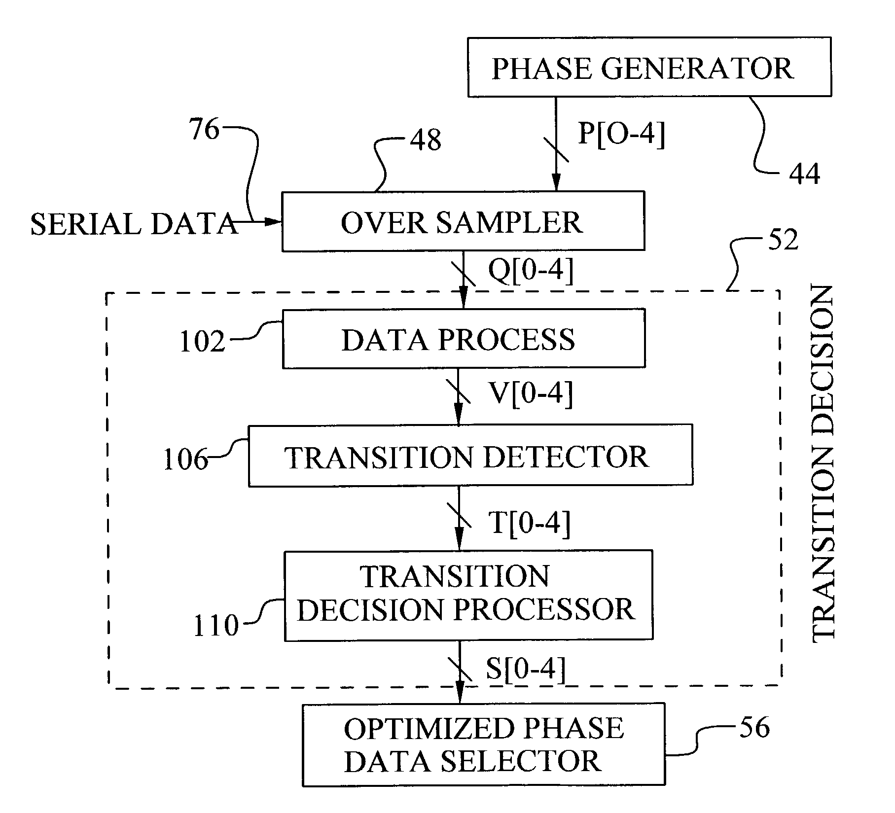
[0033]The preferred embodiments of the present invention disclose a method to produce an optimal sampling phase for recovery of a digital signal. The method uses multi-phase sampling, majority voting, and signal transition filtering to select the optimal sampling phase. Preferred embodiments of a circuit for digital signal recovery are also disclosed. It should be clear to those experienced in the art that the present invention can be applied and extended without deviating from the scope of the present invention.

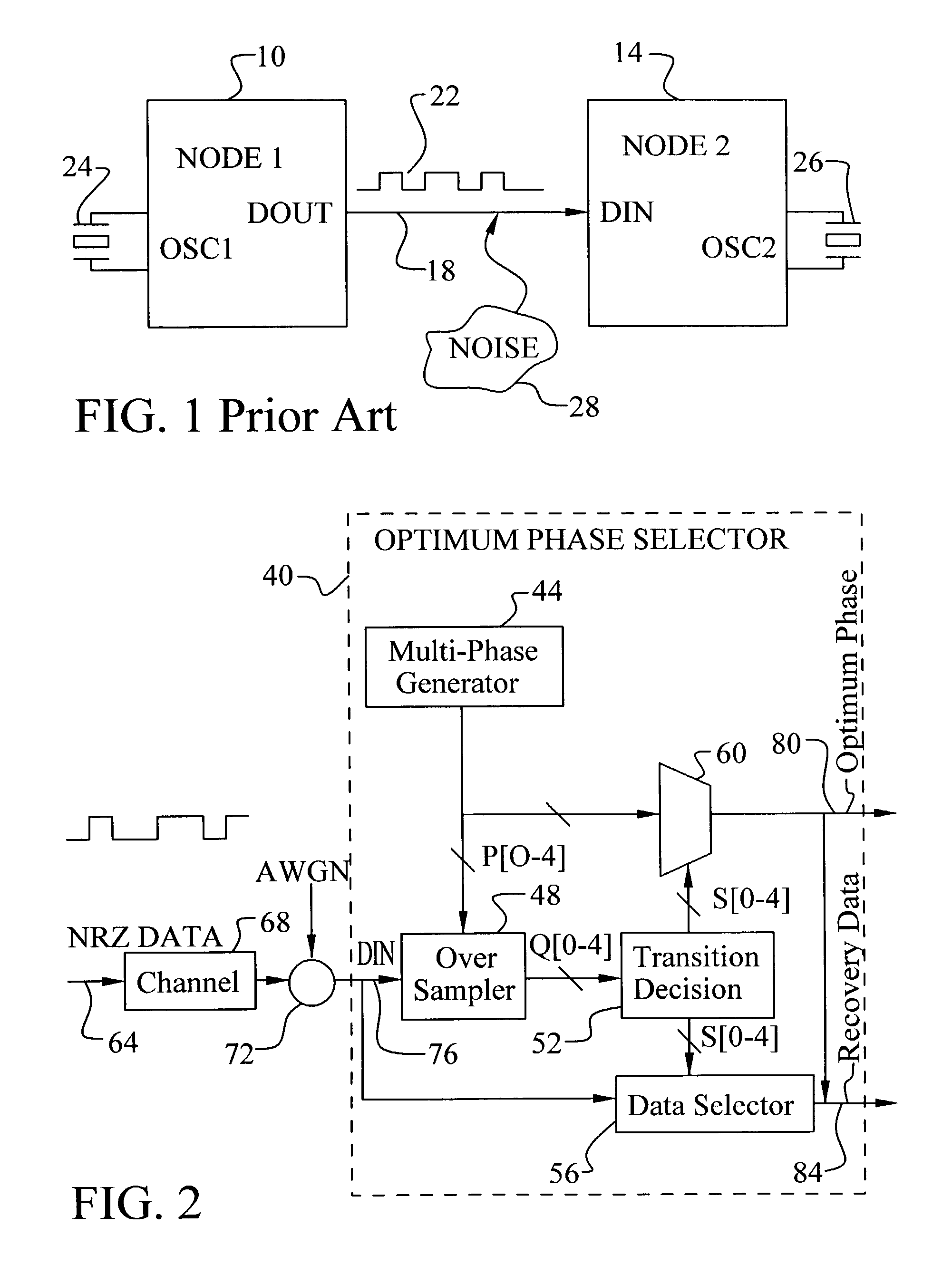
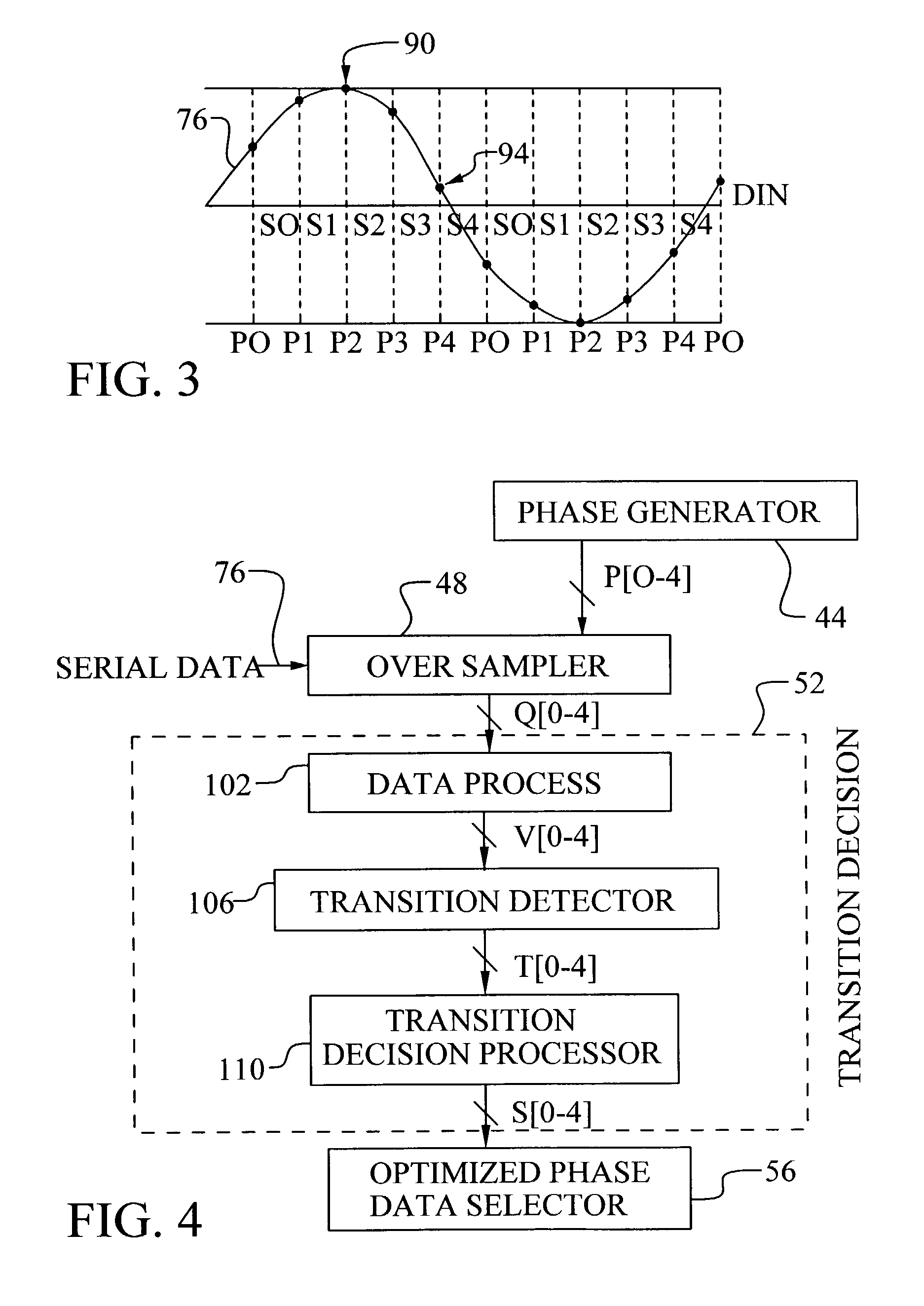
[0034]Referring now to FIG. 2, a preferred embodiment of the present invention is illustrated. Several important features of the present invention are illustrated. The preferred architecture and method of data processing will be discussed below. A digital signal recovery circuit 40 for recovery of a digital signal 76 is shown. The digital signal, DIN 76, may comprise a data bit stream or a clocking signal. In the illustration, a non-return to zero (NZR) input signal 64 is sh...


PUM


Abstract

A method and circuit to produce an optimal sampling phase for recovery of a digital signal is achieved. A digital signal is over-sampled by sampling on each phase of a multiple phase clock to generate a sample value per phase. The multiple phase clock may be generated by a DLL. A voted value is determined per phase comprising a majority value of a set of consecutive sample values. Transition phases are sensed. A transition phase is defined as two consecutive voted phases comprising different values. The transition phases are compared to a stored phase state to determine a signal shift direction. The signal shift direction is filtered to generate a state update signal. The stored phase state is updated based on the state update signal. The stored phase state corresponds to an optimal sampling phase for recovery of the digital signal.

Description

BACKGROUND OF THE INVENTION[0001](1) Field of the Invention[0002]The invention relates to digital signal processing and, more particularly, to a method and system to recover a digital signal by sampling at an optimal phase.[0003](2) Description of the Prior Art[0004]The demand for higher bit rates by the communications industry has led to the development of high speed and low cost serial link technology. Applications, such as computer-to-computer or computer-to-peripheral interconnection, are requiring high bit rates for both short distances and long distances. However, as data rates increase, losses due to cables and parasitics limit the bandwidth of data links. Improvements in data reliability and bit error rate (BER) are needed.[0005]Referring now to FIG. 1, a prior art digital communications system is shown. A first device, NODE 110, is coupled to a second device, NODE 214, by a transmission line 18. The first device 10 is sending a stream of digital data 22 out the DOUT pin. Th...

Claims


Application Information

Patent Timeline
IPC IPC(8): H04L7/00
CPCH04L7/0338
Inventor HUANG, MU-JENWEI, LINHSIANGJU, FU-SHING
Owner TAIWAN SEMICON MFG CO LTD
Why Eureka
Try Eureka