
Active controlled bottomhole pressure system & method

Inactive Publication Date: 2006-10-03
DEEP VISION
View PDF46 Cites 60 Cited by
  • Summary
  • Abstract
  • Description
  • Claims
  • Application Information

AI Technical Summary

Benefits of technology

[0013]In one embodiment of the present invention, an active pressure differential device moves in the wellbore as the drill string is moved. In an alternative embodiment, the active differential pressure device is attached to the wellbore inside or wall and remains stationary relative to the wellbore during drilling. The device is operated during drilling, i.e., when the drilling fluid is circulating through the wellbore, to create a pressure differential across the device. This pressure differential alters the pressure on the wellbore below or downhole of the device. The device may be controlled to reduce the bottomhole pressure by a certain amount, to maintain the bottomhole pressure at a certain value, or within a certain range. By severing or restricting the flow through the device, the bottomhole pressure may be increased.
[0017]In still other configurations, a positive displacement motor can drive an intermediate device such as a hydraulic motor, which drives the APD Device. Alternatively, a jet pump can be used, which can eliminate the need for a drive / motor. Moreover, pumps incorporating one or more pistons, such as hammer pumps, may also be suitable for certain applications. In still other configurations, the APD Device canb be driven by an electric motor. The electric motor can be positioned external to a drill string or formed integral with a drill string. In a preferred arrangement, varying the speed of the electrical motor directly controls the speed of the rotor in the APD device, and thus the pressure differential across the APD Device.

Problems solved by technology

This negative effect of the increase in pressure along the annulus of the well is an increase of the pressure which can fracture the formation at the shoe of the last casing.
In addition, the rate of circulation that can be achieved is also limited.
Also, due to this circulating pressure increase, the ability to clean the hole is severely restricted.
Another method for changing the density gradient in a deepwater return fluid path has been proposed, but not used in practical application.
The level of complexity of the required subsea instrumentation and controls as well as the difficulty of deployment of the system has delayed (if not altogether prevented) the practical application of the “dual gradient” system.

Method used


Image

  • Active controlled bottomhole pressure system & method
  • Active controlled bottomhole pressure system & method
  • Active controlled bottomhole pressure system & method

Examples


Embodiment Construction

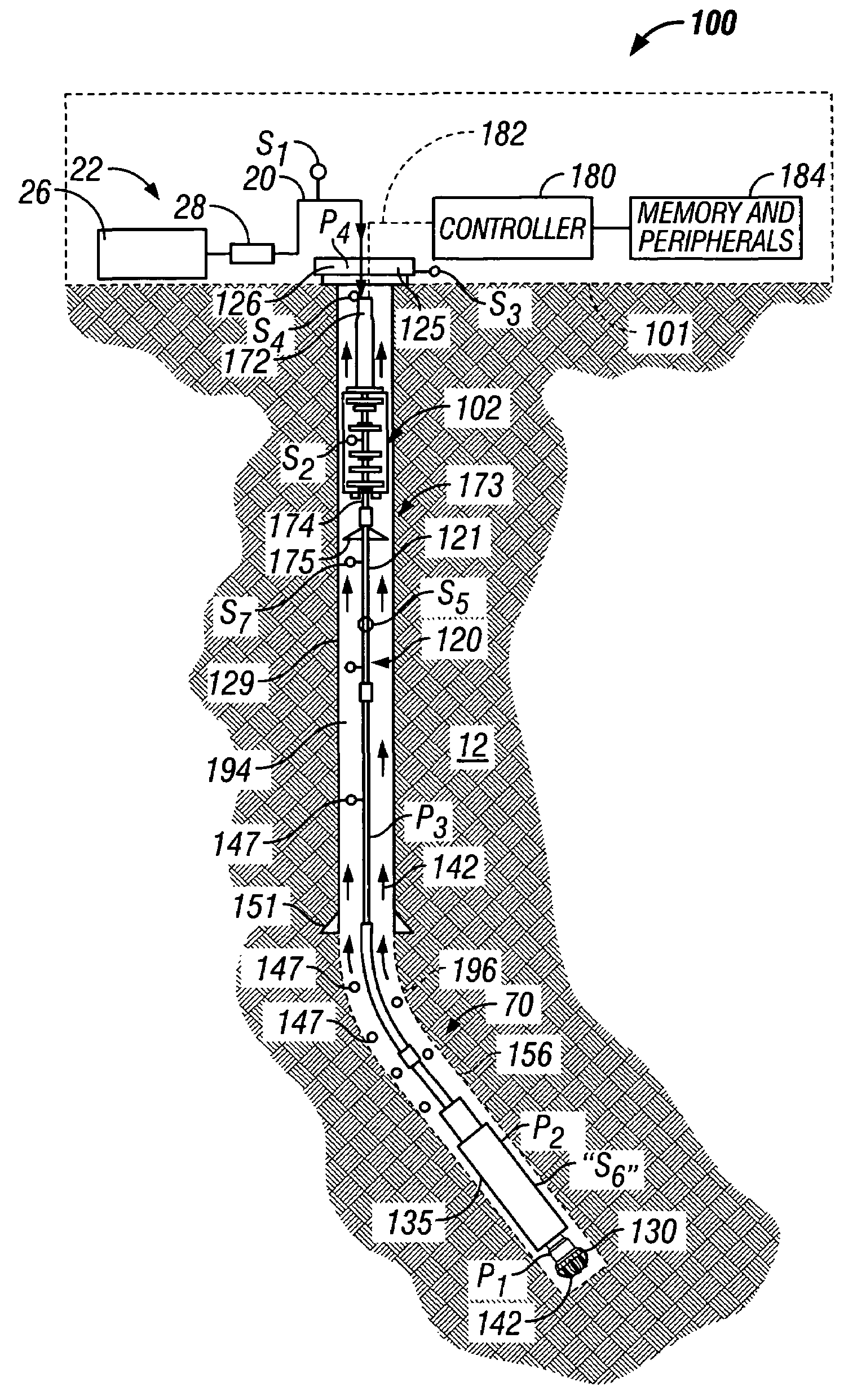
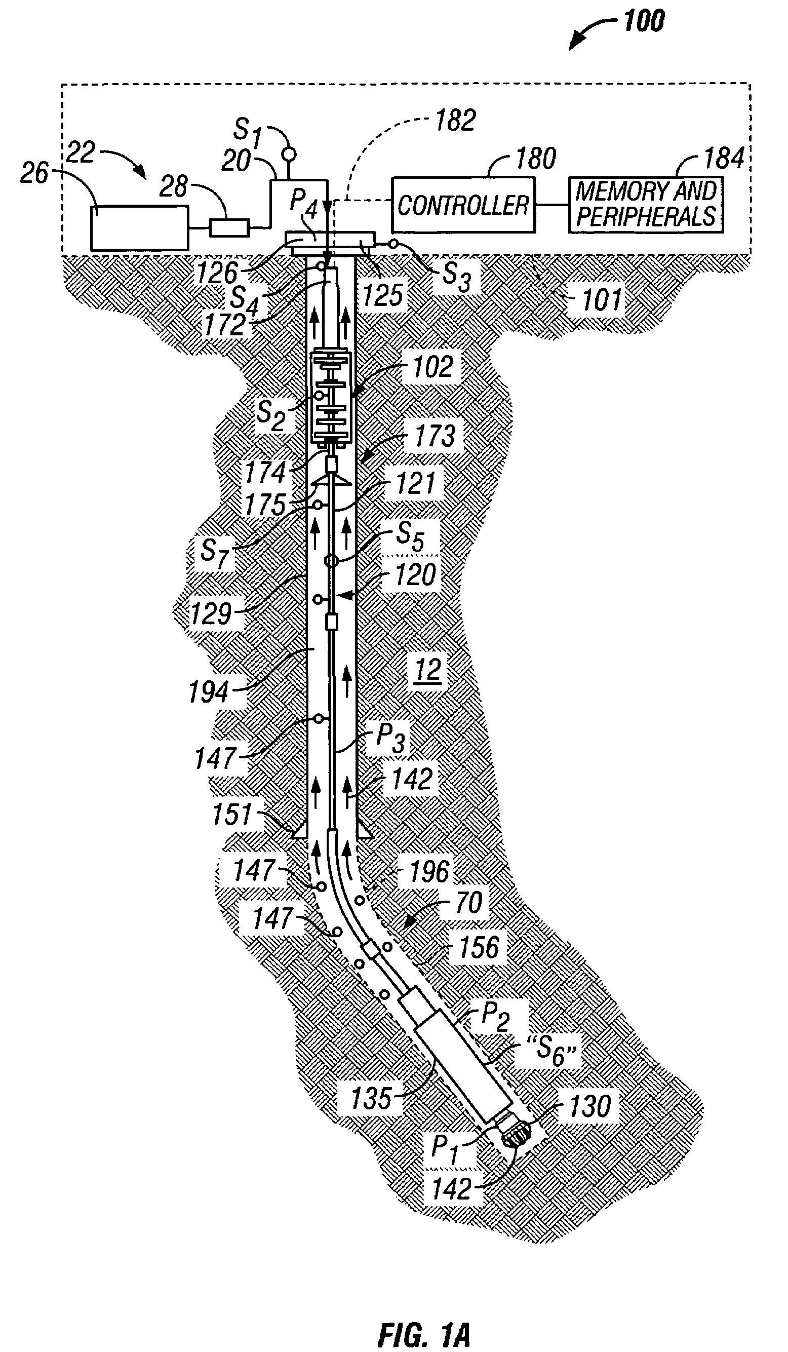
[0029]Referring initially to FIG. 1A, there is schematically illustrated a system for performing one or more operations related to the construction, logging, completion or work-over of a hydrocarbon producing well. In particular, FIG. 1A shows a schematic elevation view of one embodiment of a wellbore drilling system 100 for drilling wellbore 90 using conventional drilling fluid circulation. The drilling system 100 is a rig for land wells and includes a drilling platform 101, which may be a drill ship or another suitable surface workstation such as a floating platform or a semi-submersible for offshore wells. For offshore operations, additional known equipment such as a riser and subsea wellhead will typically be used. To drill a wellbore 90, well control equipment 125 (also referred to as the wellhead equipment) is placed above the wellbore 90. The wellhead equipment 125 includes a blow-out-preventer stack 126 and a lubricator (not shown) with its associated flow control.

[0030]This...


PUM


Abstract

A wellbore drilling system has an umbilical that carries a drill bit in a wellbore. Drilling fluid pumped into the umbilical discharges at the drill bit bottom and returns through an annulus between the umbilical and the wellbore carrying entrained drill cuttings. An active differential pressure device (APD device), such as a jet pump, turbine or centrifugal pump, in fluid communication with the returning fluid creates a differential pressure across the device, which alters the pressure below or downhole of the device. The APD device can be driven by a positive displacement motor, a turbine, an electric motor, or a hydraulic motor. A controller controls the operation of the APD device in response to programmed instructions and / or one or more parameters of interest detected by one or more sensors. A preferred system is a closed loop system that maintains the wellbore at under-balance condition, at-balance condition or over-balance condition.

Description

CROSS-REFERENCE TO RELATED APPLICATIONS[0001]This application is a continuation of U.S. patent application Ser. No. 10 / 251,138 filed Sep. 20th, 2002, now abandoned which takes priority from U.S. provisional patent application Ser. No. 60 / 323,803 filed on Sep. 20, 2001, titled “Active Controlled Bottomhole Pressure System and Method.”[0002]This application is a continuation-in-part of U.S. patent application Ser. No. 10 / 716,106 filed on Nov. 17th, 2003, now U.S. Pat. No. 6,854,532 which is a continuation of U.S. patent application Ser. No. 10 / 094,208, filed Mar. 8, 2002, now U.S. Pat. No. 6,648,081 granted on Nov. 18, 2003, which is a continuation of U.S. application Ser. No. 09 / 353,275, filed Jul. 14, 1999, now U.S. Pat. No. 6,415,877, which claims benefit of U.S. Provisional Application No. 60 / 108,601, filed Nov. 16, 1998, U.S. Provisional Application No. 60 / 101,541, filed Sep. 23, 1998, U.S. Provisional Application No. 60 / 092,908, filed, Jul. 15, 1998 and U.S. Provisional Applicat...

Claims


Application Information

Patent Timeline
IPC IPC(8): E21B7/00B63B21/50E21B4/00E21B4/02E21B7/128E21B7/28E21B17/20E21B19/00E21B19/09E21B19/22E21B21/00E21B21/08E21B33/076E21B43/12
CPCB63B21/502E21B7/002E21B7/128E21B7/28E21B17/206E21B19/002E21B19/09E21B19/22E21B21/00E21B21/001E21B21/08E21B33/076E21B43/121E21B43/122E21B2021/006E21B4/006E21B4/02E21B21/085E21B4/04
Inventor ARONSTAM, PETERKRUEGER, VOLKERKRUEGER, SVENGRIMMER, HARALDFINCHER, ROGERWATKINS, LARRYFONTANA, PETER
Owner DEEP VISION
Features
  • Generate Ideas
  • Intellectual Property
  • Life Sciences
  • Materials
  • Tech Scout
  • Unparalleled Data Quality
  • Higher Quality Content
  • 60% Fewer Hallucinations
Learn More