Pliant SRAF for improved performance and manufacturability

a technology of sraf and manufacturability, applied in the field of manufacturing processes, can solve the problems of degrading process windows, imposing formidable problems, and challenging conventional optical lithography, and achieve the effect of improving lithographic performance and increasing the coverage of srafs

Inactive Publication Date: 2006-10-03
GLOBALFOUNDRIES INC
View PDF10 Cites 192 Cited by
  • Summary
  • Abstract
  • Description
  • Claims
  • Application Information

AI Technical Summary

Benefits of technology

[0015]The present invention provides a method for increasing coverage of SRAFs in a given layout. In particular, the present invention provides a set of possible SRAF placement and sizing rules for a given pitch, ranked according to some figure of merit. The figure of merit may include, for example, process window (PW) area, mask error factor (MEF), depth of focus (DOF), percent coverage, etc., or combinations thereof. During SRAF placement, rather than using only the single “best” SRAF solution that optimizes the figure of merit (as is done in the prior art), the method of the present invention successively evaluates the fit of a plurality of different SRAF solutions to find the SRAF solution, or combination of SRAF solutions, which most improves lithographic performance while avoiding manufacturability problems, such as mask constraint violations.

Problems solved by technology

Even as exposure wavelengths continue to decrease, and numerical apertures continue to increase, conventional optical lithography is still challenged by resolution below k1=0.5.
Approaching k1=0.5 imposes formidable problems due to image quality degradation associated with the loss of increasing numbers of diffracted orders.
The drawback of OAI is that pitches other than the primary pitch will print with degraded process windows.
In addition, since there are no discrete diffracted orders for isolated lines, there is little improvement of resolution for isolated lines as compared to densely pitched lines and spaces.
Real layouts, however, are more complicated and consist of features that may have finite length, corners, or T-junctions (i.e., 2D geometry).
As it is very difficult to enumerate all the possible combination of geometries that may occur in a real layout, SRAF placement rules are not currently derived specially for any of these cases.
It is expected that many SRAFs will not meet these constraints; those that do not are typically discarded.
Unfortunately, the “cleanup” of an SRAF design containing un-manufacturable SRAF solutions may negatively impact lithographic performance (e.g., reduce process window, reduce yield, etc.).
Those areas not covered may suffer a decreased process window and can potentially reduce yield.
The effect of discarding the SRAFs that violate the manufacturing constraints is clear: incorrect line bias and an increase in sensitivity to focus error.
The latter problem, however, is not easily correctable.

Method used


Image

  • Pliant SRAF for improved performance and manufacturability
  • Pliant SRAF for improved performance and manufacturability
  • Pliant SRAF for improved performance and manufacturability

Examples


Embodiment Construction

[0034]In the following description, numerous specific details may be set forth to provide a thorough understanding of the present invention. However, it will be obvious to those skilled in the art that the present invention may be practiced without such specific details. In other instances, well known features may have been shown in block diagram form in order not to obscure the present invention in unnecessary detail.

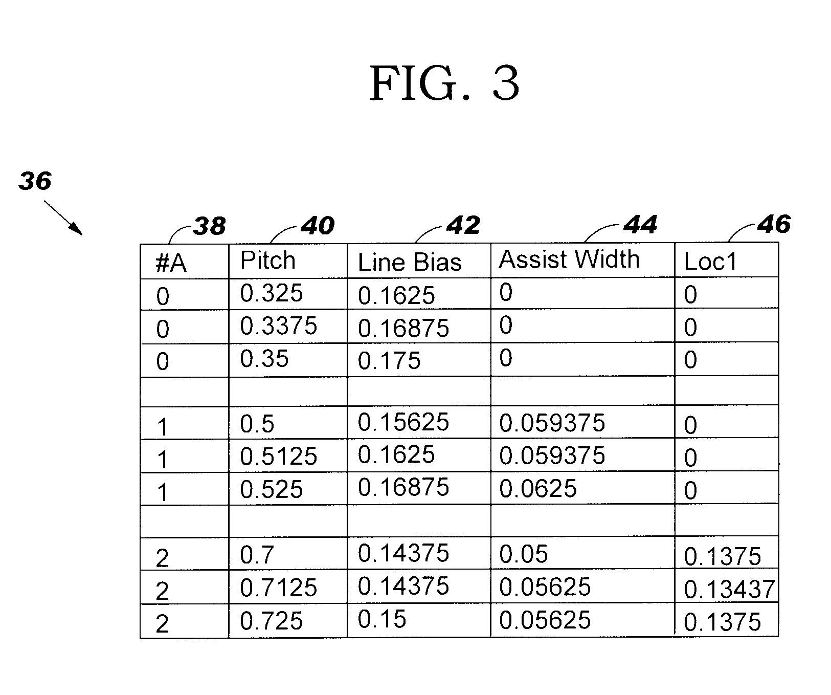
[0035]The present invention provides a method for increasing coverage of SRAFs in a given layout. In particular, the present invention provides a set of possible SRAF placement and sizing rules for a given pitch, ranked according to some figure of merit. The figure of merit may include, for example, process window (PW) area, mask error factor (MEF), depth of focus (DOF), percent coverage, etc., or combinations thereof. During SRAF placement, rather than using only the single “best” SRAF solution that optimizes the figure of merit (as is done in the prior art), the meth...


PUM

PropertyMeasurementUnit
densityaaaaaaaaaa
transparentaaaaaaaaaa
sizeaaaaaaaaaa

Abstract

A method for increasing coverage of subresolution assist features (SRAFs) in a layout. A set of possible SRAF placement and sizing rules for a given pitch is provided, ranked according to some figure of merit. During SRAF placement, the fit of a plurality of different SRAF solutions is successively evaluated to find the SRAF solution, or combinations thereof, which most improves lithographic performance while avoiding manufacturability problems. In general, the method comprises: obtaining a plurality of SRAF configurations for the layout; ranking the SRAF configurations based on a figure of merit; applying a highest ranked SRAF configuration to the layout; applying a predetermined number of lower ranked SRAF configurations to the layout; and selecting SRAF features from at least one of the applied SRAF configurations to provide the optimal SRAF configuration for the layout.

Description

BACKGROUND OF INVENTION[0001]The present invention relates in general to manufacturing processes that require lithography and, in particular, to methods of designing photomasks and optimizing lithographic and etch processes used in microelectronics manufacturing.[0002]There is a continuing effort to reduce the dimensions of integrated circuit (IC) devices, and this has required greater precision in the tools used to manufacture IC devices. IC devices are designed using computer-aided design (CAD) or technology-computer-aided design (TCAD) layout tools which allow designers and manufacturers to plan the layout of circuits on a semiconductor wafer. The finished designs must be transferred to the wafer in a manner that allows device features to be produced by various processes of etching, depositing, implanting, and the like. This is done by applying a photoresist (also known as resist) layer to the surface of the wafer and then exposing the photoresist to radiation transmitted through...

Claims


Application Information

Patent Timeline
Patent Type & Authority Patents(United States)
IPC IPC(8): G03F9/00G06F17/50G03C5/00
CPCG03F1/36
Inventor GORDON, RONALD L.GRAUR, IOANA C.LIEBMANN, LARS W.
Owner GLOBALFOUNDRIES INC
Why Eureka
Try Eureka