[0013]It is an
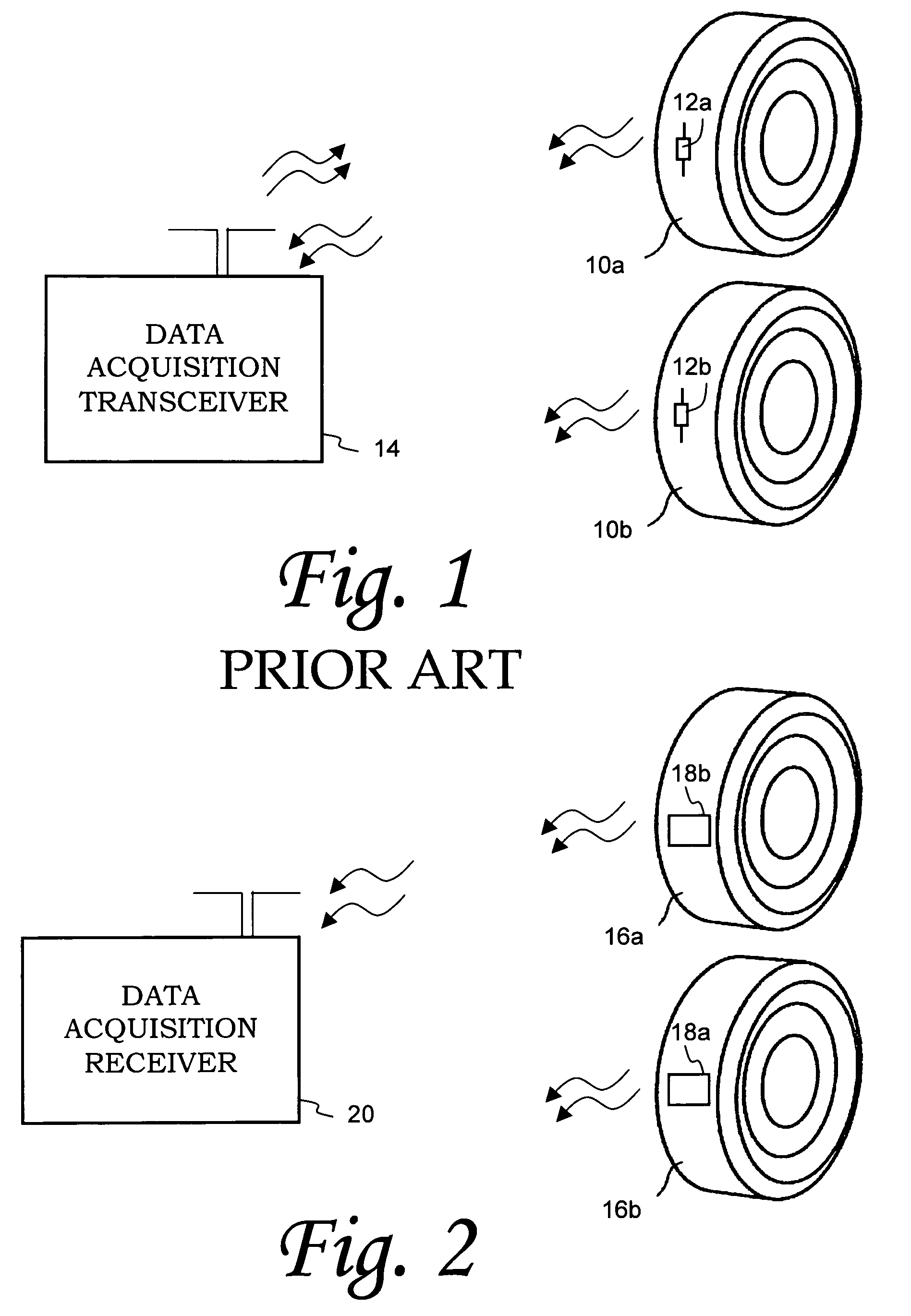
advantage of some exemplary embodiments of the present invention to provide an actively operating electronic assembly that includes a condition-responsive device, which may correspond to an acoustic wave device. In accordance with such active operation, an acoustic wave sensor is provided with a proximal means for energizing the sensor such that it can actively transmit to a remote
receiver location. This eliminates the need for
transmitter electronics in a corresponding interrogator, resulting in a large reduction in the power requirements for such
data acquisition electronics.
[0014]In further accordance with select embodiments of the present invention, yet another
advantage corresponds to the fact that the electromagnetic source used to energize the condition-responsive device is in close proximity to such device. Thus, a mere fraction of the energy emitted with the
transceiver interrogation method is required to be provided to the condition-responsive device. Alternatively, the same amount of energy as in the
transceiver interrogation method could be provided to the condition-responsive device, thus yielding an output signal with a much
higher power level, enabling greater read distances for a remote data
receiver.
[0015]Another
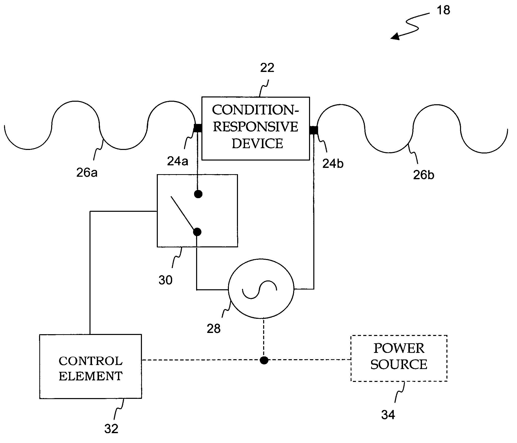
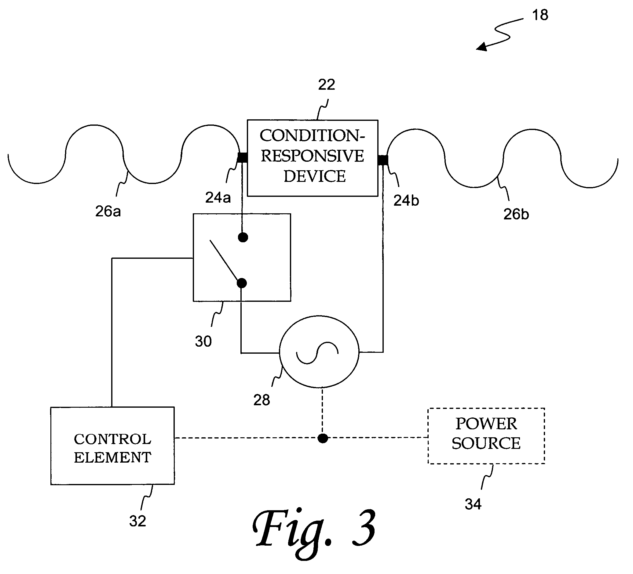
advantage of aspects of the present invention is that a condition-responsive device, such as an acoustic wave sensor, can be provided with modulation functionality. By providing a condition-responsive device in selective connection with an RF source via switching and control elements, the condition-responsive device effectively transmits a pulsed
data signal, wherein portions of the
data signal also preferably include resonant frequency information for the condition-responsive device. This provides the ability for a condition-responsive device to operate not only as a sensor device that transmits information corresponding to certain physical parameters of a tire such as
temperature and pressure, but also as a device that can transmit data modulated onto the
carrier signal provided by the RF source by
selective control of a switching element. Additional advantages may be achieved in accordance with specific communication protocols, such as Direct-Sequence
Spread Spectrum (DSSS), which may be employed in such data modulation and RF signaling techniques.
[0016]Yet anther advantage of embodiments of the present
subject matter is to provide an anti-collision solution for multiple condition-responsive devices operating in the same energizing field. By providing a controllable switching element in parallel with a condition-responsive device, the switching element can selectively short out the condition-responsive device,
cloaking the device from the interrogating
electromagnetic field, preventing it from being remotely energized. Thus, after a condition-responsive device transmits information to a remote receiver, it can be cloaked for some predetermined amount of time to reduce the chance of data collision from multiple transmitting condition-responsive devices. By implementing
handshaking signals to respective controllers of the
cloaking switch elements in multiple electronics assemblies in accordance with the present technology, additional
cloaking and / or anti-collision arbitration can be accomplished.
[0021]A still further embodiment of the present technology corresponds to a tire assembly with integrated sensing features designed to measure and transmit information relating to preselected tire conditions, and may include a pneumatic tire structure, an acoustic wave device, an antenna, an RF source and a controllable switching element. The condition-responsive device is configured to sense information about at least one physical parameter associated with the pneumatic tire structure, such as temperature and / or pressure, while the antenna is preferably connected to the condition-responsive device for facilitating the transmission of RF output signals indicating the at least one sensed physical parameter. The RF source may also be selectively connected to the condition-responsive device via the controllable switching element. The frequency of the RF source is preferably inclusive of potential resonant frequencies associated with the condition-responsive device.

