
Apparatus for signaling that a predetermined time value has elapsed

a signaling apparatus and predetermined time value technology, applied in the field of electromechanical circuit technology, can solve the problems of increasing the area requirement, inaccuracy and variation, capacitors with very high capacitance, etc., and achieve the effect of accurate production and accurate operation

Inactive Publication Date: 2006-10-03
POLARIS INNOVATIONS
View PDF9 Cites 0 Cited by
  • Summary
  • Abstract
  • Description
  • Claims
  • Application Information

AI Technical Summary

Benefits of technology

[0010]One advantage of the present invention is that the accuracy of the apparatus for signaling that a predetermined time value has elapsed is essentially determined by the accuracy of a centrally generated clock signal which is used for the measurement of time values. By way of example, if a plurality of apparatuses for signaling that a predetermined time value has elapsed are used in distributed fashion over a chip, then the accuracy of the signaling that a respective time value has elapsed depends, in contrast to the prior art, not on the accuracy of each individual local delay circuit, which has, for example, a current mirror in each case but rather essentially on the accuracy of the clock signal. Thus, by way of example, all that is required is an accurately produced and accurately operating clock generator which generates a clock signal precisely and centrally and supplies it to apparatuses—distributed over a chip—for signaling that a time value has elapsed.
[0011]A further advantage of the present invention is that, by virtue of the fact that a clock signal is used for measuring that a predetermined time value has elapsed, it is possible to compensate for temperature variations and production variations of the circuit elements of the apparatus for signaling that a predetermined time value has elapsed, by variation of the clock signal.
[0012]A further advantage of the present invention is that the supplied time values, such as e.g. delay times, can be varied by changing the period duration of the clock signal which is used for measuring time values.
[0013]A further advantage of the present invention is that the measurement of a time value can be initiated at an arbitrary instant by each individual apparatus—positioned on a chip—for signaling that a time value has elapsed, independently of the phase angle of a centrally generated clock signal.
[0014]Advantageous developments and improvements of the apparatus specified in Claim 1 and of the integrated circuit specified in Claim 22 are found in the subclaims.
[0015]In accordance with one preferred development of the apparatus of the present invention, the apparatus furthermore has a device for control which controls the device for acquiring and storing the amplitude value of a clock signal in such a way that said device only acquires and stores amplitude values of a clock signal which are greater than a predetermined minimum amplitude value and which are less than a predetermined maximum amplitude value.

Problems solved by technology

One disadvantage of such circuits for controlling delay times is that variations and inaccuracies in the transistor parameters of the current mirrors and the capacitor parameters lead to inaccuracies and variations during the generation of the delay times. Such variations are caused for example by temperature and production variations, but also, in particular, by variations in the capacitor parameters over a chip.
A further disadvantage of circuits for controlling delay times is that capacitors having very high capacitances have to be used for controlling long delay times. This on the one hand increases the area requirement and the outlay of the circuits and on the other hand leads to inaccuracies in the determination of delay times with the aid of a threshold value due to the flat charging characteristic of capacitors having a large capacitance.

Method used


Image

  • Apparatus for signaling that a predetermined time value has elapsed
  • Apparatus for signaling that a predetermined time value has elapsed
  • Apparatus for signaling that a predetermined time value has elapsed

Examples


Embodiment Construction

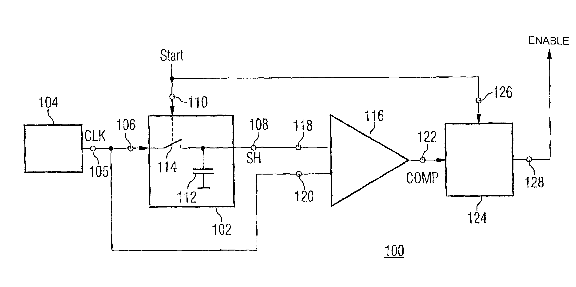
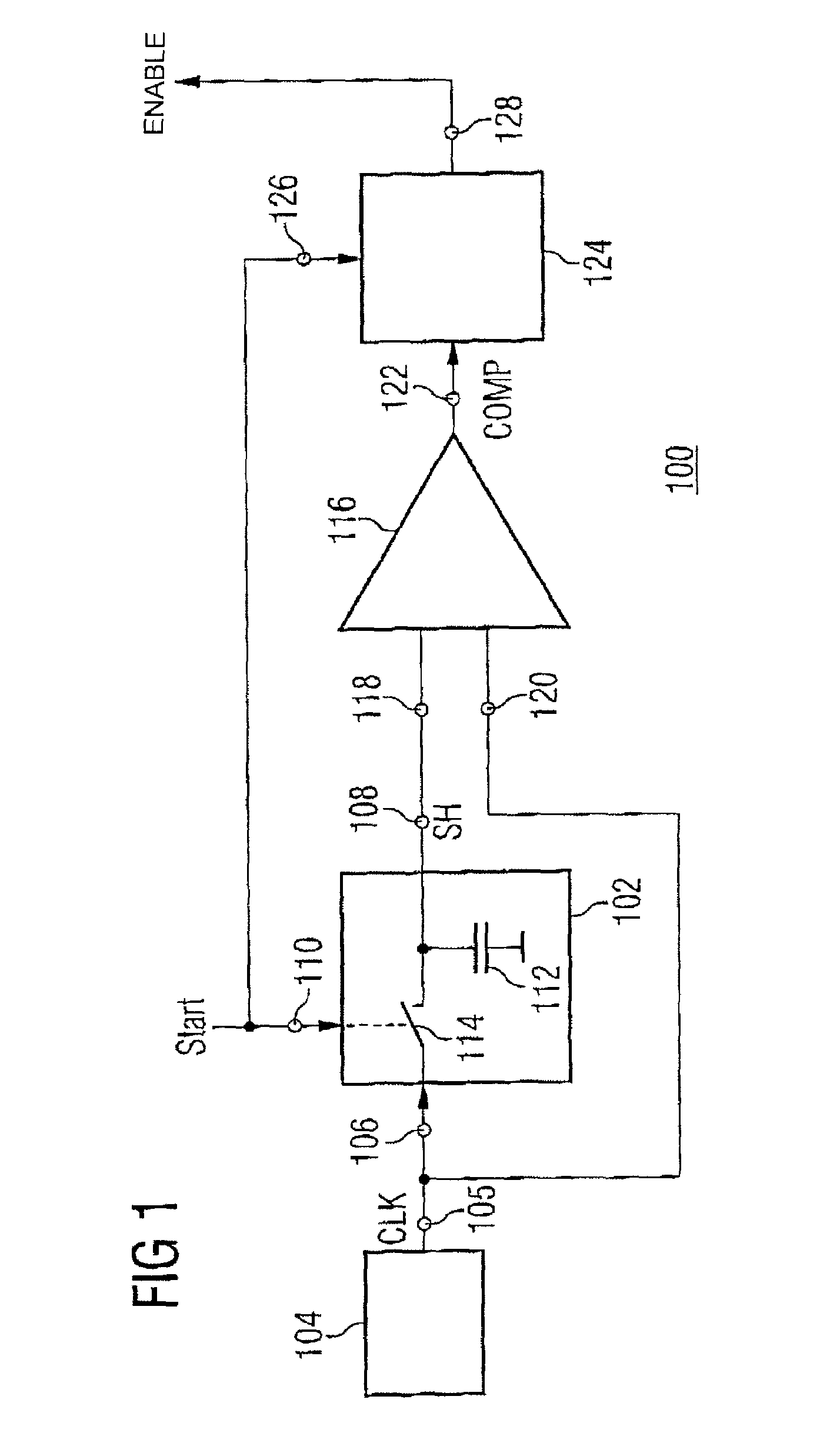
[0043]FIG. 1 shows a first exemplary embodiment of an apparatus for signaling that a predetermined time value has elapsed, according to the present invention. The predetermined time value is a time value which can be programmed into the apparatus 100 and corresponds to a time value after the elapsing of which with regard to a start time value the apparatus 100 outputs a signal in order to signal this elapsing. The predetermined time value is, for example, a delay time value for a memory module after the elapsing of which an enable signal is output in order to control read-in and -out operations for data into and from memory cells of the memory module.

[0044]The apparatus 100 has a device 102 for acquiring and storing the amplitude value of a clock signal at an acquisition instant in the temporal profile of the clock signal. The clock signal used is a time-continuous analog signal which generally has a monotonically rising profile of the amplitude value during one section of a period ...


PUM


Abstract

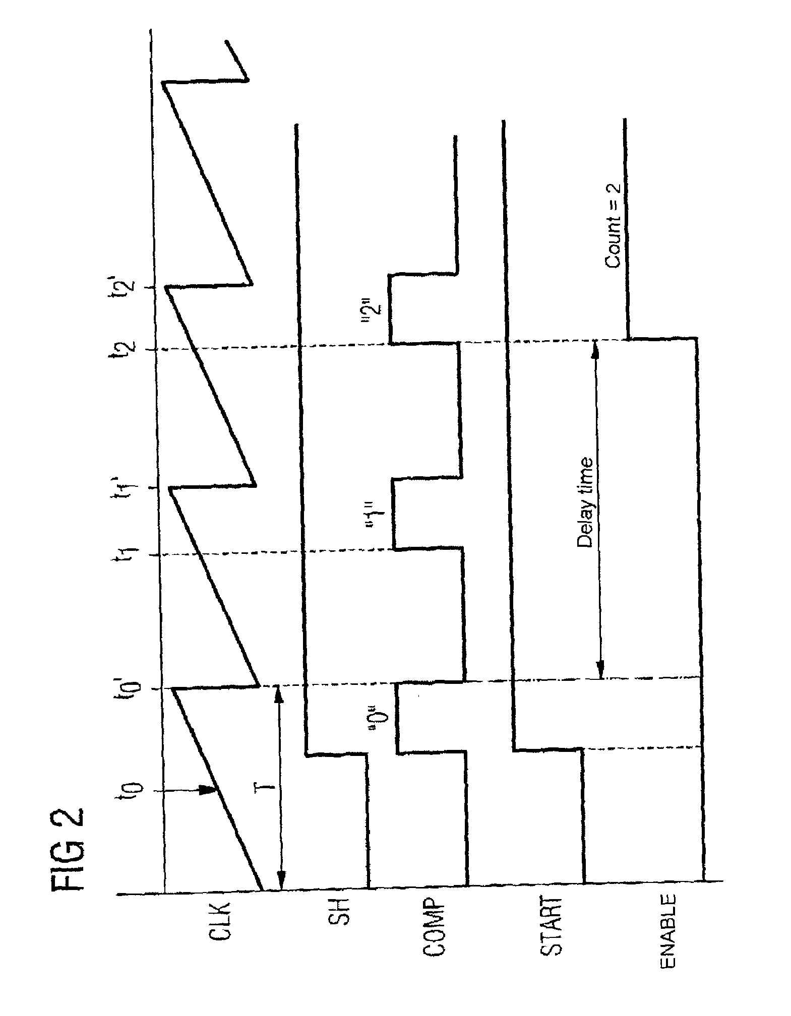
The present invention provides an apparatus for signaling that a predetermined time value has elapsed, having a device for acquiring and storing the amplitude value of a clock signal at an acquisition instant in the temporal profile of the clock signal. A device is provided for continuously comparing the acquired and stored amplitude value of the clock signal with an instantaneous amplitude value of the clock signal and for outputting a comparison signal which has a first logic state if the instantaneous amplitude value of the clock signal is less than the stored amplitude value and has a second logic state if the instantaneous amplitude value of the clock signal is greater than the stored amplitude value. A device is also provided for counting the number of logic states of the comparison signal which occur after the acquisition instant, and for signaling that the predetermined time value has elapsed if the counted number of logic states is equal to a predetermined number of logic states which corresponds temporally to the predetermined time value.

Description

[0001]The present invention relates to an apparatus for signaling that a predetermined time value has elapsed, and in particular to an apparatus for signaling that a delay time value for integrated circuits has elapsed.TECHNICAL FIELD[0002]In electronic circuit technology or in integrated circuits, a precise control of delay times or delays is required. Such delay times are used for example for the addressing of memory cells in memory components, such as dynamic random access memories (DRAMS), during the reading in and out of data.BACKGROUND ART[0003]In the prior art, delay times are usually controlled with the aid of a simple circuit having a constant current source, a capacitor, which is connected in series with the current source and which stores the charge of a current over time with a characteristic charging curve, and a comparator, which is connected in parallel with the capacitor and which compares the voltage generated by a charge in the capacitor with a threshold value. The...

Claims


Application Information

Patent Timeline
Patent Type & Authority Patents(United States)
IPC IPC(8): H04L7/00G04F1/00G11C27/02H03K5/00H03K5/08H03K5/13
CPCG04F1/005G11C27/024H03K5/08H03K5/13H03K2005/00247
Inventor EGGERS, GEORG ERHARDKLIEWER, JORGSCHNEIDER, RALFWIRTH, NORBERT
Owner POLARIS INNOVATIONS
Learn More