High pressure pump having replaceable plunger/valve cartridges

a high-pressure pump and plunger technology, which is applied in the direction of machines/engines, liquid fuel engines, positive displacement liquid engines, etc., can solve the problems of extreme stress on system components, difficult disassembly process, and limited design of pump system frame assemblies, so as to achieve the effect of changing the pump outpu

Inactive Publication Date: 2006-10-17
NEW LANTAO BUS
View PDF11 Cites 32 Cited by
  • Summary
  • Abstract
  • Description
  • Claims
  • Application Information

AI Technical Summary

Benefits of technology

[0011]By mounting an alternative cartridge within the pump, the pump output is varied. The pump output is primarily determined by the diameter of the plunger, the length of the plunger stroke, the number of cylinders, and the speed of the pump. A specific cartridge allows replacement of all the components which interface with a plunger of a particular diameter such that a change in pump output is readily achieved by cartridge replacement.
[0012]Replacement of worn components is also readily achieved by replacement of the entire cartridge. Such replacement is readily achieved in a field environment. The cartridge itself may be further repaired in a shop environment where the cartridge is refurbished through replacement of just the worn, yet more difficult to replace components.
[0013]Accordingly, the present invention provides a pump system which allows convenient access to high wear internal components and which provides field replaceable components which readily converts the pump to achieve a variable pump displacement and pressure. The present invention further provides replaceable components which are long-lasting while providing consistent high pressure operating.

Problems solved by technology

Due in part to the cyclical operation between high and low pressure, the system components undergo extreme stresses.
Although providing a strong and robust system, such a disassembly process may be relatively time consuming and difficult in a field environment.
Moreover, pump system frame assemblies are typically design limited with regard to the predetermined flow rate and displacements.
This may be somewhat inefficient in terms of transport cost, duplicate system expense, and maintenance.

Method used


Image

  • High pressure pump having replaceable plunger/valve cartridges
  • High pressure pump having replaceable plunger/valve cartridges
  • High pressure pump having replaceable plunger/valve cartridges

Examples


Embodiment Construction

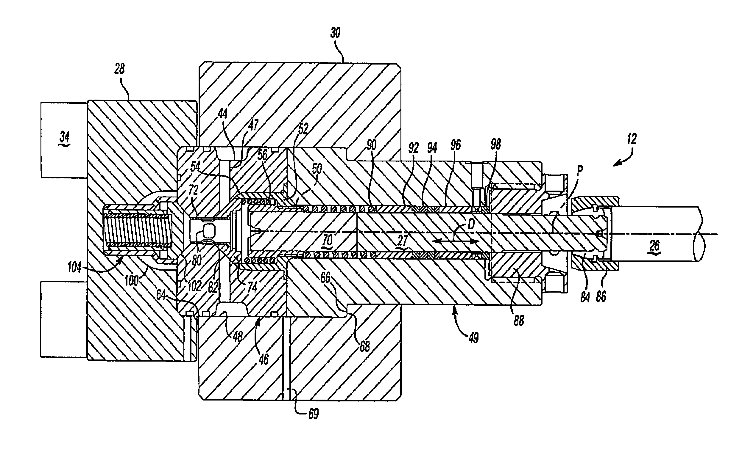
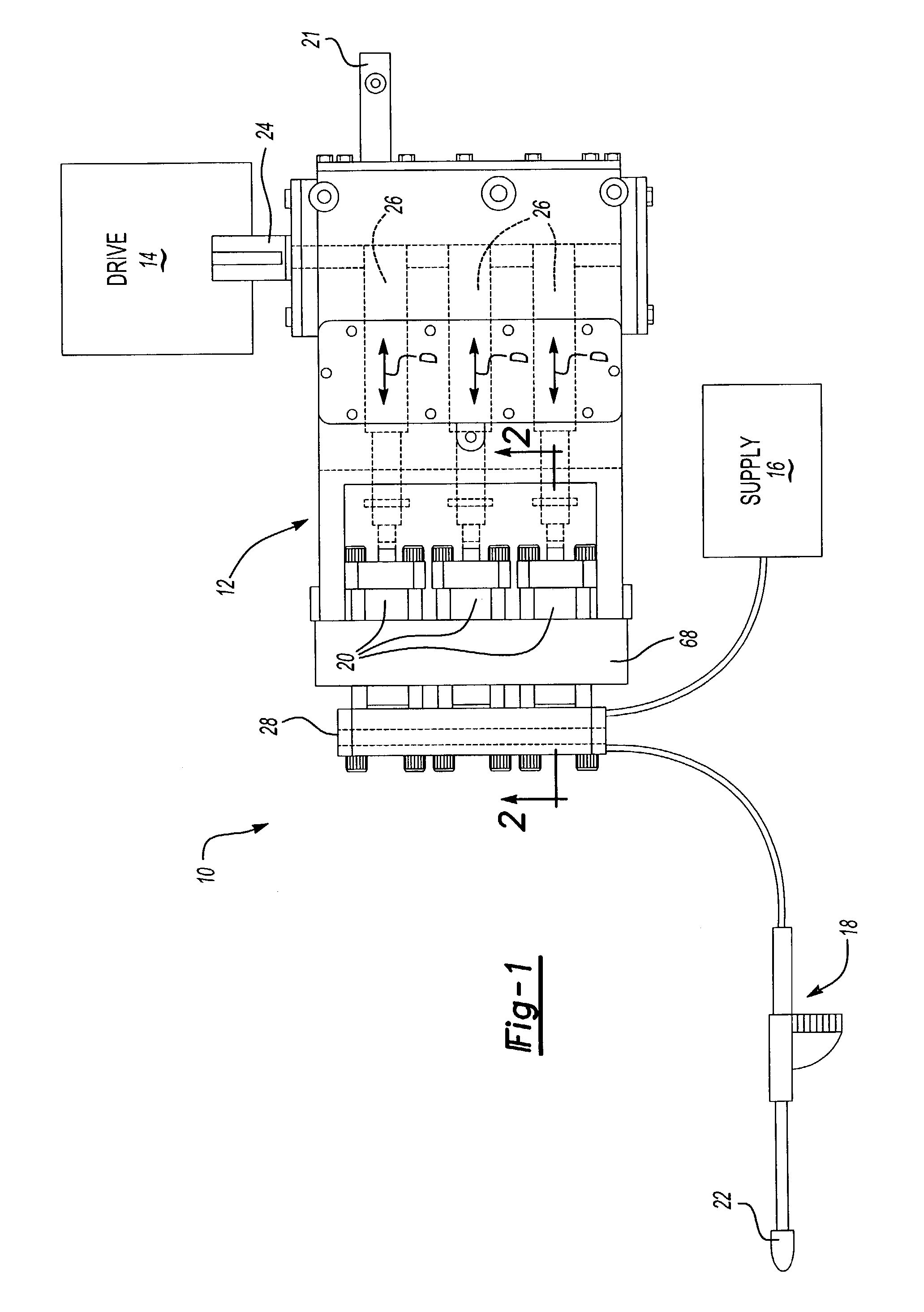
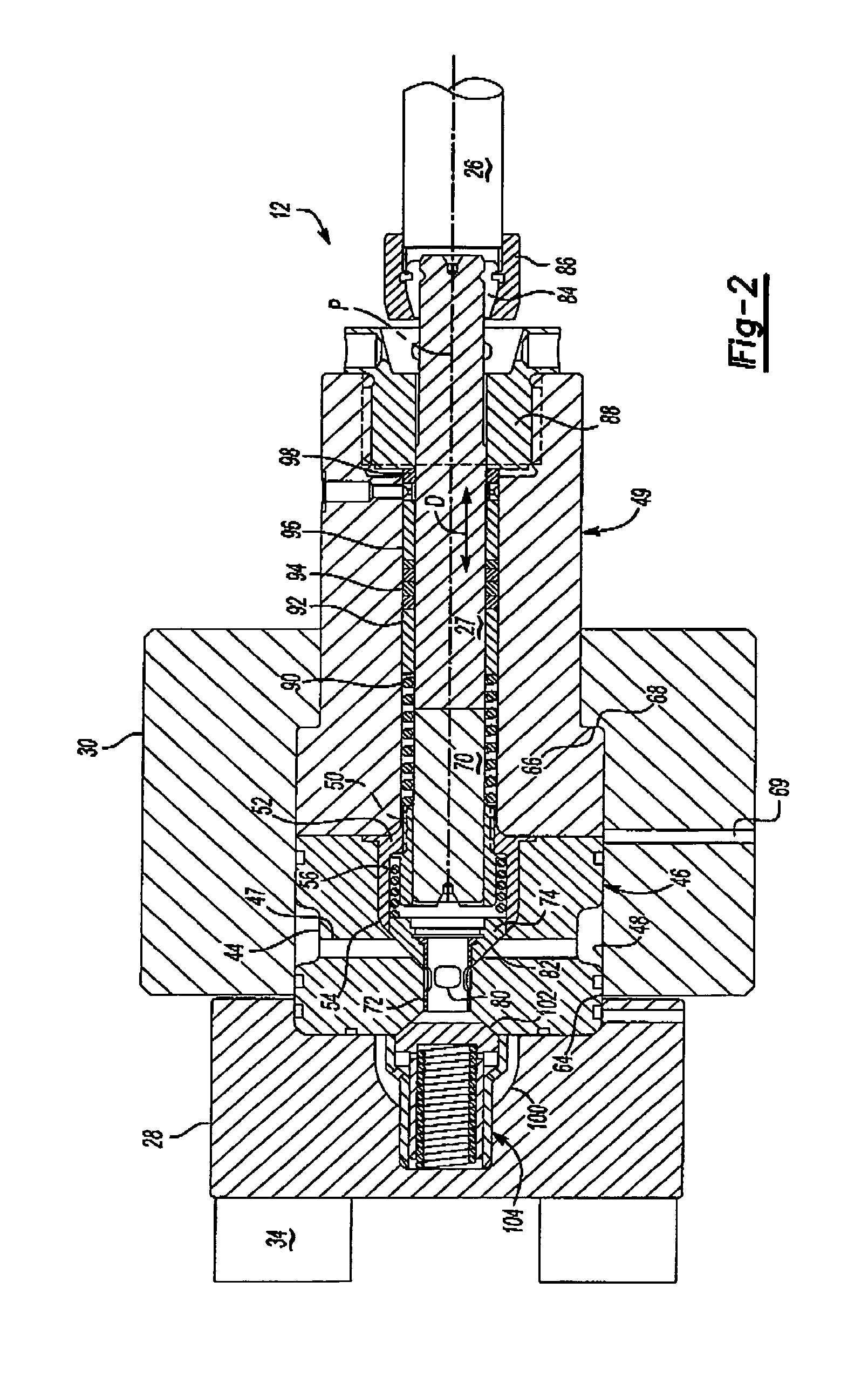
[0026]FIG. 1 illustrates a high pressure fluid jetting system 10. The system 10 generally includes a fluid cylinder pump 12, a drive assembly 14, a pressurized liquid supply 16 and an applicator gun 18. Preferably, the fluid cylinder pump 12 operates to selectively jet water from the gun 18 at a variable pressure and flow rate through replacement of internal pressure cartridges 20 (also illustrated in FIG. 2). A by-pass valve 21 provides for fine-tuning of the system pressure.

[0027]The drive assembly 14 includes a diesel engine or electric powered motor which drives a rotatable drive shaft 24. Drive shaft 24 drives a triple plungers 26 which are reciprocally driven in the direction of doubled headed arrows D along axis P. Plungers 26 communicate fluid from the supply 16 to the gun 18, such that the fluid is discharged form the nozzle 22 at a pressure based upon the selected cartridge 20.

[0028]As the nozzle 22 of the gun 18 wears, by pass valve 21 may be adjusted automatically or man...


PUM


Abstract

A high pressure fluid jetting system generally includes a fluid cylinder pump, a drive assembly, a pressurized liquid supply and an applicator gun. The drive assembly includes a diesel engine or electric powered motor which drives a rotatable drive shaft. The drive shaft drives a triple plunger which are reciprocally driven. A valve seat assembly and a cylindrical cartridge seal assembly define a cartridge which contains a reciprocating plunger shaft. The primary high wear parts are located therein. The cartridge is retained within the manifold cartridge opening yet is readily accessible by removal of the manifold. The pump output is primarily determined by the diameter of the plunger the length of the stroke, the number of cylinders, and the speed of the pump. A specific cartridge allows replacement of all the components which interface with a plunger shaft of a predetermined diameter such that a change in pump output or repair is readily achieved by straightforward cartridge replacement.

Description

BACKGROUND OF THE INVENTION[0001]The present invention relates to a high pressure fluid pump system, and more particularly to a fluid pump system with a hinged manifold which provides for replacement of high wear components as a cartridge without complete pump system disassembly.[0002]Systems that perform water jetting operations such as surface preparation, cutting cleaning, coating removal and other operations are known. The systems typically use a fluid cylinder having reciprocating plungers to force the fluid out of an applicator at extremely high pressure. As the plungers reciprocate within the fluid cylinder, the fluid cylinder and components thereof cycle between atmospheric and maximum system pressure.[0003]Due in part to the cyclical operation between high and low pressure, the system components undergo extreme stresses. The life span of some high wear components may be reduced in relation to the other system components. Typically, the high wear components are located deep ...

Claims


Application Information

Patent Timeline
Patent Type & Authority Patents(United States)
IPC IPC(8): F04B39/10F16K31/12F04B53/22
CPCF04B53/22Y10T137/7835Y10T137/7852
Inventor FORREST, JAMIE A.
Owner NEW LANTAO BUS
Why Eureka
Try Eureka