

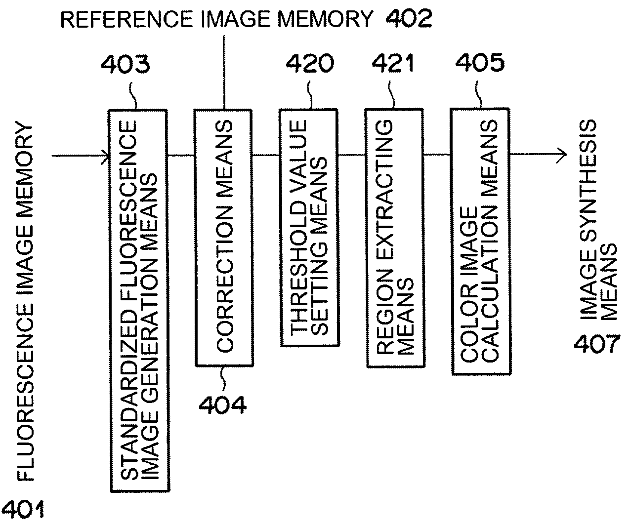
Method and apparatus for standardized fluorescence image generation
a fluorescence image and fluorescence intensity technology, applied in the field of standardized fluorescence image generation, can solve the problems of difficult discrimination between diseased tissue and normal tissue, inability to accurately discriminate the tissue state of living tissue, and inability to accurately perform the calculation of standardized value, etc., to achieve the improvement of the s/n ratio of a calculated standardized value, accurate performance, and easy correction function
- Summary
- Abstract
- Description
- Claims
- Application Information
AI Technical Summary
Benefits of technology
Problems solved by technology
Method used
Image

Examples
first embodiment
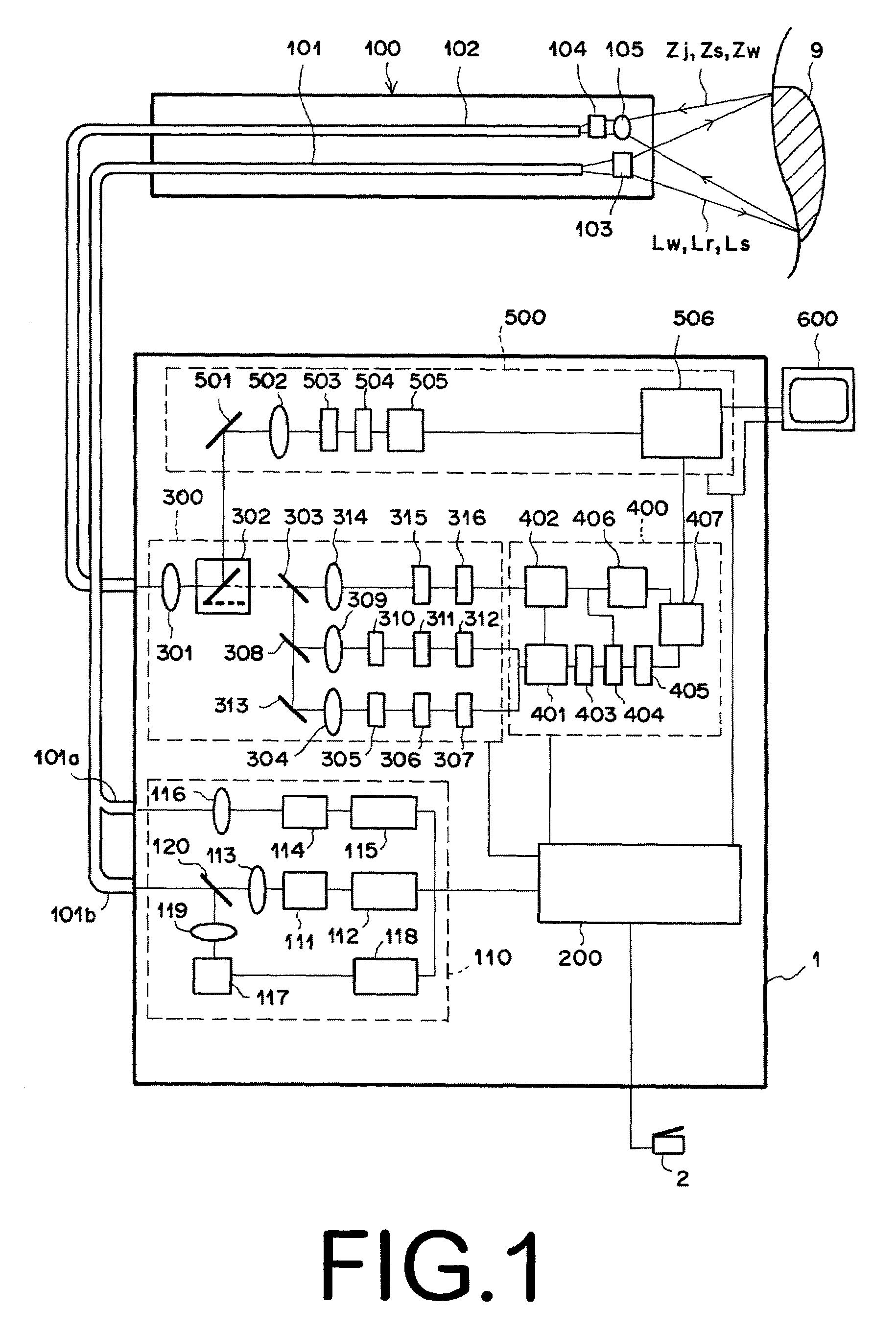
[0056]Hereinafter, specific embodiments of the present invention will be described with reference to the attached figures. FIG. 1 shows the schematic structure of a fluorescence endoscope that employs a standardized image generation apparatus for carrying out the standardized image generation method according to the present invention.
[0057]The fluorescence endoscope according to the present embodiment comprises: an endoscope insertion portion 100 for insertion into the suspected locus of disease of the patient; an image signal processing portion 1 for processing the data obtained from living tissue by the endoscope insertion portion 100 as image signals; and a monitor 600 for displaying as a visible image the signals processed by the image signal processing portion 1.
[0058]The image signal processing portion comprises: an illumination unit 110 equipped with three light sources for emitting a white light Lw for obtaining a standard image, an excitation light Le for obtaining an fluor...
second embodiment
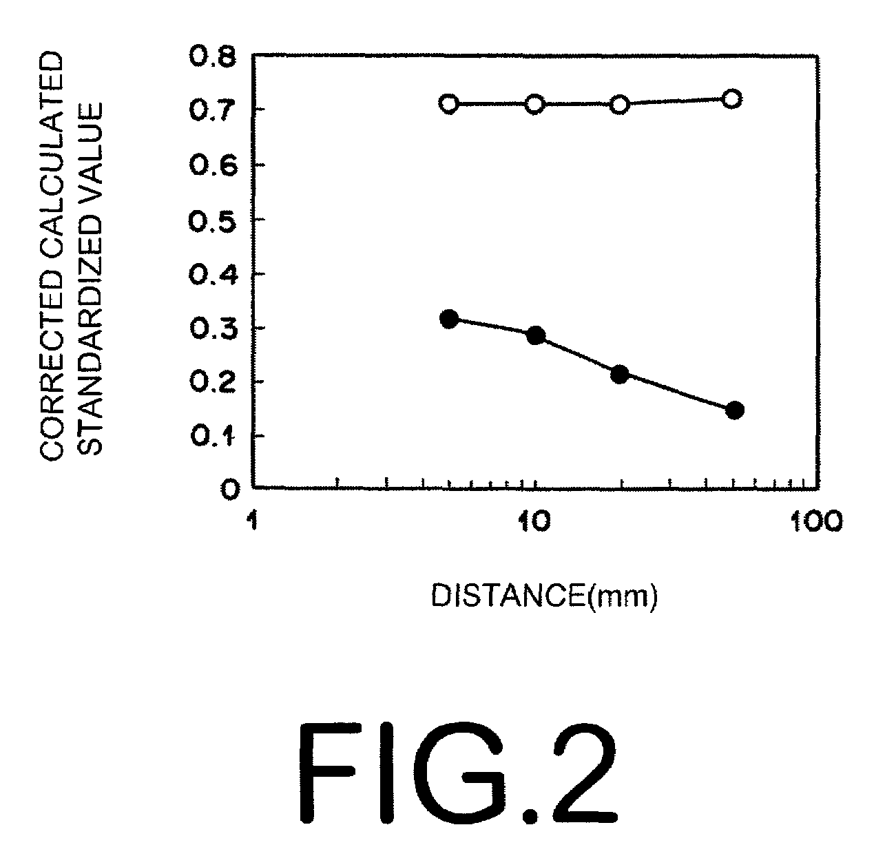
[0116]Further, with regard to the second embodiment, the correction function was derived from the relationship between the calculated standardized values based on the fluorescence images and the pixel values of wide bandwidth fluorescence image. However, the derivation of the correction function is not limited to this method. The correction function may alternatively be derived from the relationship between the pixel values of the narrow band fluorescence image and the calculated standardized values, or the relationship between the sums of the pixel values of the narrow bandwidth fluorescence image and the wide bandwidth fluorescence image and the calculated standardized values.
[0117]In the first and second embodiments described above, a correction function is derived based on normal or diseased tissue, a corrected calculated standardized value is calculated employing the correction function thus derived, a threshold value is set based on the corrected calculated standardized value,...
PUM
 Abstract
Description
Claims
Application Information