Design build test cycle reduction

a technology of design build and test cycle, applied in the field of contact lens, lens mold & insert design and manufacturing arts, can solve the problems of not being able to model 100% accurately what is actually happening in the physical process of making contact lenses, custom developed design software can be very complex and evolve, and achieves the effect of minimizing errors, fast finding any system flaws, and 100% accuracy

Inactive Publication Date: 2006-10-17
JOHNSON & JOHNSON VISION CARE INC
View PDF24 Cites 35 Cited by
  • Summary
  • Abstract
  • Description
  • Claims
  • Application Information

AI Technical Summary

Benefits of technology

[0029]The 3D modeling system according to the invention further includes built-in revision controls that are 100% accurate, and the data can be shared readily amongst many different types of customers. The ability to view the 3D models and the 100% accuracy of the solid models minimizes the errors that can be present in such complex software systems. This also helps to quickly find any flaws in the system, and allows modifications to be made very quickly. The data output and export options of 3D systems can link dire

Problems solved by technology

This, however may not model 100% accurately what is actually happening in the physical process of making contact lenses.
This analysis yields new figures for shrinkage and expansion, as produced by operating the Pilot Line and may result in a contact lens manufactured not according to design specifications.
From the process described so far, it is common that that all iterations have to go back to the Lens Design Group at step 15 because the custom developed design software “links” relating the lens to the molds and the molds to the inserts and cores, for regulatory control reasons, is generally not available to anyone outside this group.
The custom developed design software can be very complex and evolve over many years.
The above system is a very time consuming exercise, and can take up to eight months and up to six iterations to develop and prove a new contact lens design and have the product available to the consumer.
Due to its complexity a

Method used


Image

  • Design build test cycle reduction
  • Design build test cycle reduction
  • Design build test cycle reduction

Examples


Embodiment Construction

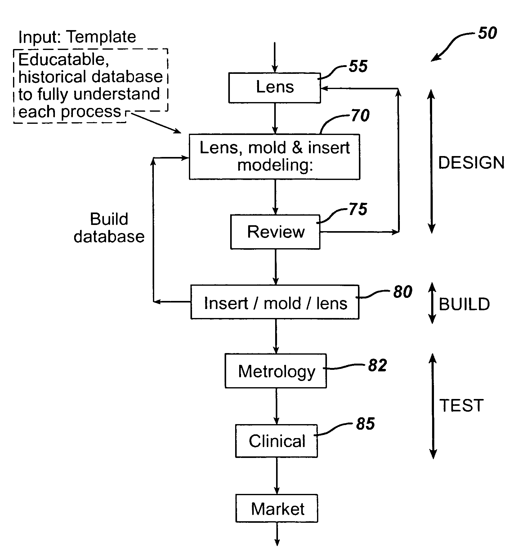
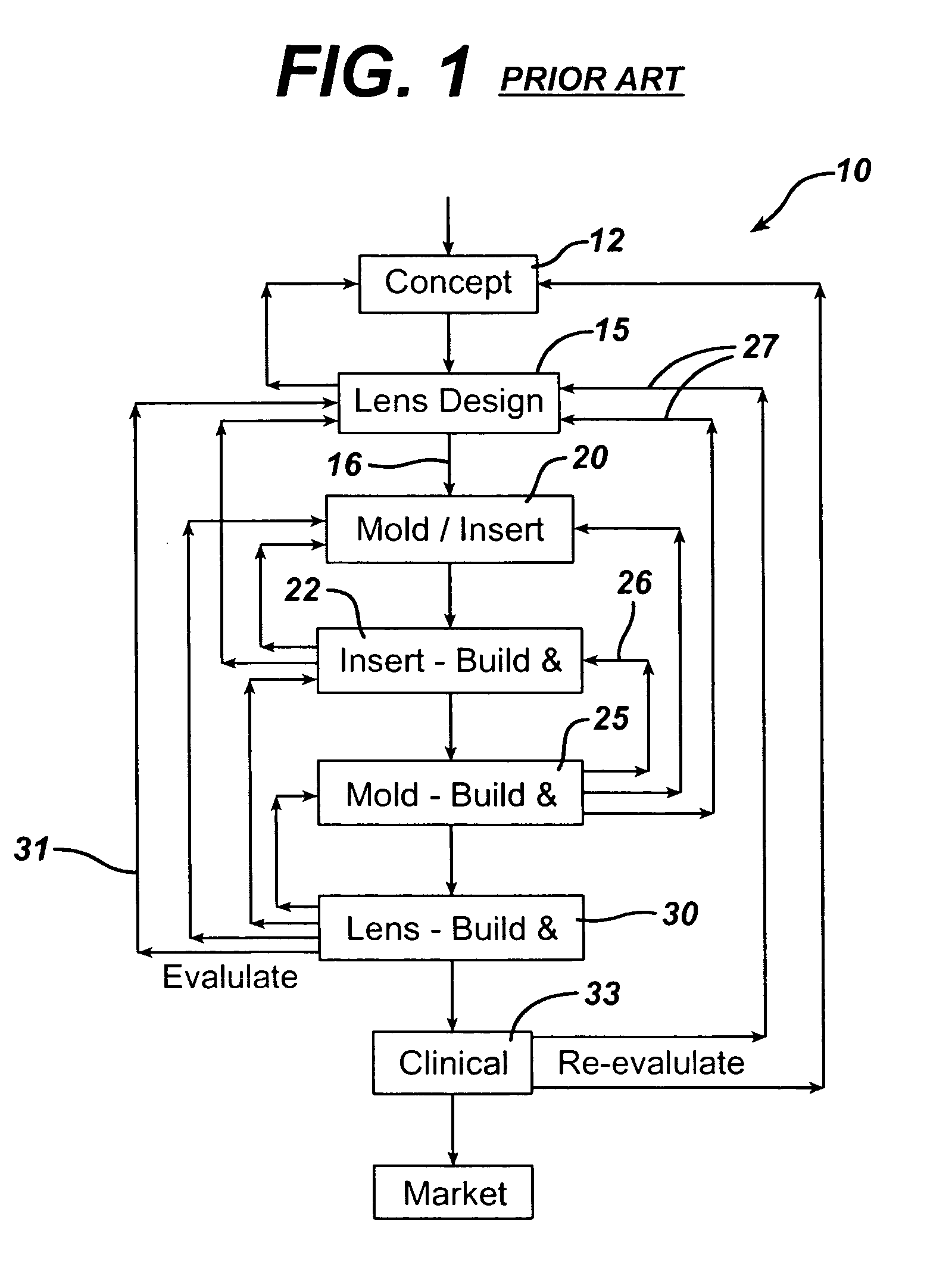
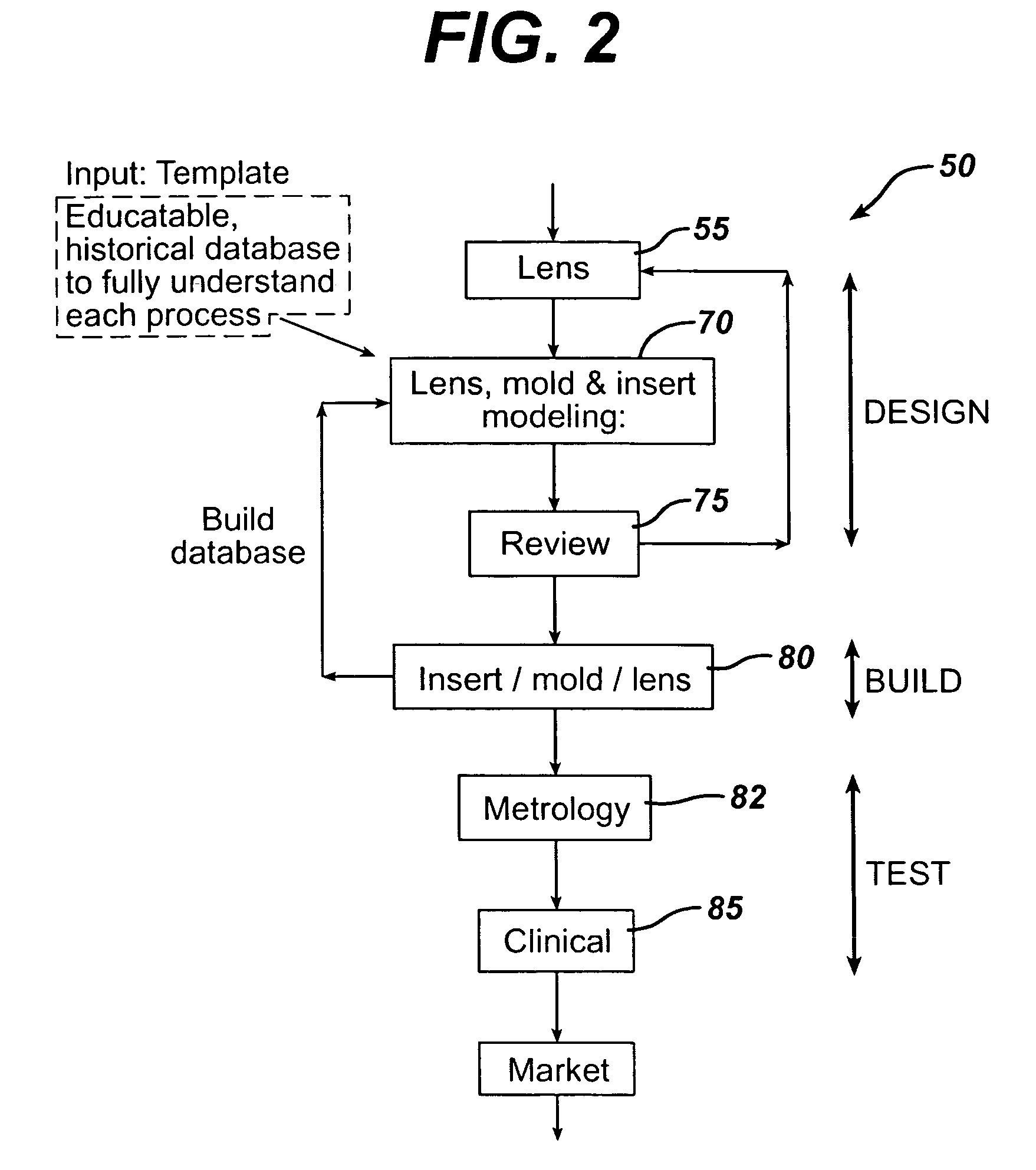
[0038]The robust ophthalmic lens design and modeling system providing efficiencies for rapid design and build and test (DBT) manufacturing phases according to the invention is illustrated in FIG. 2. As shown in FIG. 2, the design and build and test (DBT) manufacturing phases is substantially streamlined than the prior art system of FIG. 1 due to the benefits of the modeling system efficiencies. Particularly, after a lens design step 55, there is performed a lens model generating step 70 for the generation of a lens modeling template associated with that design and which comprises all the manufacturing data required for its manufacture within specifications. Preferably, the template specifies data including: lens design parameters (e.g., power, diameter, base curve and center thickness, cylinder, various radii and zones, etc.), FC and BC core surface specifications, and manufacturing process parameters (such as shrinkage of plastic from the insert, for example, and / or hydration of th...


PUM

PropertyMeasurementUnit
Shrinkageaaaaaaaaaa
Reduction potentialaaaaaaaaaa

Abstract

An ophthalmic lens design and modeling system comprises a user interface providing functionality for generating a template associated with a desired lens design to be manufactured, the template comprising design information sufficient for generating three-dimensional (3D) models of lens, and 3D models of associated components required for lens manufacture in an ophthalmic lens manufacturing system. The system further includes functionality for generating and/or specifying linking information, via the user interface, that governs the physical behavior of lens design features included in said template in accordance with one or more process parameters affecting lens manufacture and manufacture of associated components in an ophthalmic lens manufacturing system. The use of the template and design and linking information therein thus facilitates rapid lens modeling and lens manufacturing operations with greater accuracy, thereby reducing lens design build and test (DBT) cycle time.

Description

[0001]This is a non-provisional application that claims priority from U.S. Provisional application Ser. No. 60 / 372,738 filed Apr. 12, 2002FIELD OF THE INVENTION[0002]The invention relates generally to contact lens, lens mold & insert design and manufacturing arts, and particularly a design methodology and tool for reducing the Design-Build-Test Cycle Times of new and existing ophthalmic lens products, including mold inserts and mold items implemented in contact lens design and manufacturing processes.DISCUSSION OF THE PRIOR ART[0003]Prior to manufacturing a contact lens, a design concept must be generated and parameter / process verification must be established. In practice,a research and Development Group is responsible for developing and producing lens design concepts, and proving the manufacturability of them through prototype manufacture, clinical trials and scale-up activities.[0004]A Product Development Group consisting of (mainly) Lens Design, Plastic Processing and the Tooling...

Claims


Application Information

Patent Timeline
IPC IPC(8): B29C39/00G02BG02C7/02G05B19/4097G06F17/50G06F19/00
CPCG05B19/4097G06F19/3437G06F19/3406G05B2219/35028G05B2219/45157G06F19/324G05B2219/49008G16H20/00G16H40/63G16H50/50Y02P90/02
Inventor WILDSMITH, CHRISTOPHERLUST, VICTORPEREZ, JOSE L.DAMODHARAN, KRISHROY, JEFFREY M.DANIEL, JASONPINELLA, DAVID F.
Owner JOHNSON & JOHNSON VISION CARE INC
Why Eureka
Try Eureka