
Robust Group III light emitting diode for high reliability in standard packaging applications

a light-emitting diode, high-reliability technology, applied in the direction of basic electric elements, electrical apparatus, semiconductor devices, etc., can solve the problems of degrading the electronic performance of the device, affecting the use of vertical devices, and affecting the optical and electrical performan

Inactive Publication Date: 2006-10-24
CREE INC
View PDF34 Cites 35 Cited by
  • Summary
  • Abstract
  • Description
  • Claims
  • Application Information

AI Technical Summary

Problems solved by technology

In contrast, the insulating character of sapphire prevents its use in vertical devices.
Accordingly, it has been determined that in commercial use (the term “commercial” generally refers, but is not limited, to a product that is manufactured and sold on an inventory basis), they suffer from particular types of physical and chemical breakdown that eventually degrade the electronic performance of the devices.
More specifically, it has become apparent that under normal environmental conditions, in which LED lamps are operated at or above room temperature and under normal conditions of humidity and other environmental factors, the epitaxial layers, ohmic contacts and associated passivation layers tend to interact with one another resulting in degraded optical and electrical performance.
The degradation problem appears to be particularly acute in those devices that include p-type GaN as their top layer, with an ohmic contact to that p-type layer.
A particular form of degradation that is highly undesirable in LED lamps is an increase in forward voltage over time (VF degradation).
VF degradation can lead to higher operating temperatures and increased power consumption over the life of the device.
Thus, in some commercial versions of blue LEDs made from Group III nitrides, the packaging itself is very specific and robust because the LED chip being packaged is relatively fragile even under normal environmental circumstances.
The more widespread introduction of GaN-based LEDs has demonstrated, however, that such a general selection of materials is inappropriate, and that the resulting LEDs degrade much more rapidly than is otherwise appropriate for useful commercial devices.
Although the devices described in the '409 application demonstrated improved capabilities, some degradations problems persist.

Method used


Image

  • Robust Group III light emitting diode for high reliability in standard packaging applications
  • Robust Group III light emitting diode for high reliability in standard packaging applications
  • Robust Group III light emitting diode for high reliability in standard packaging applications

Examples


Embodiment Construction

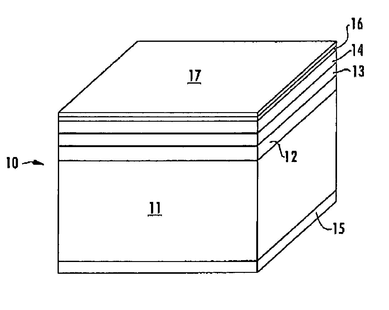
[0034]The present invention is a physically robust light emitting diode that offers high reliability in standard packaging and will withstand high temperature and high humidity conditions.

[0035]As noted in the background, ohmic contacts must be protected from physical, mechanical, environmental and packaging stresses to prevent degradation of Group III nitride LEDs.

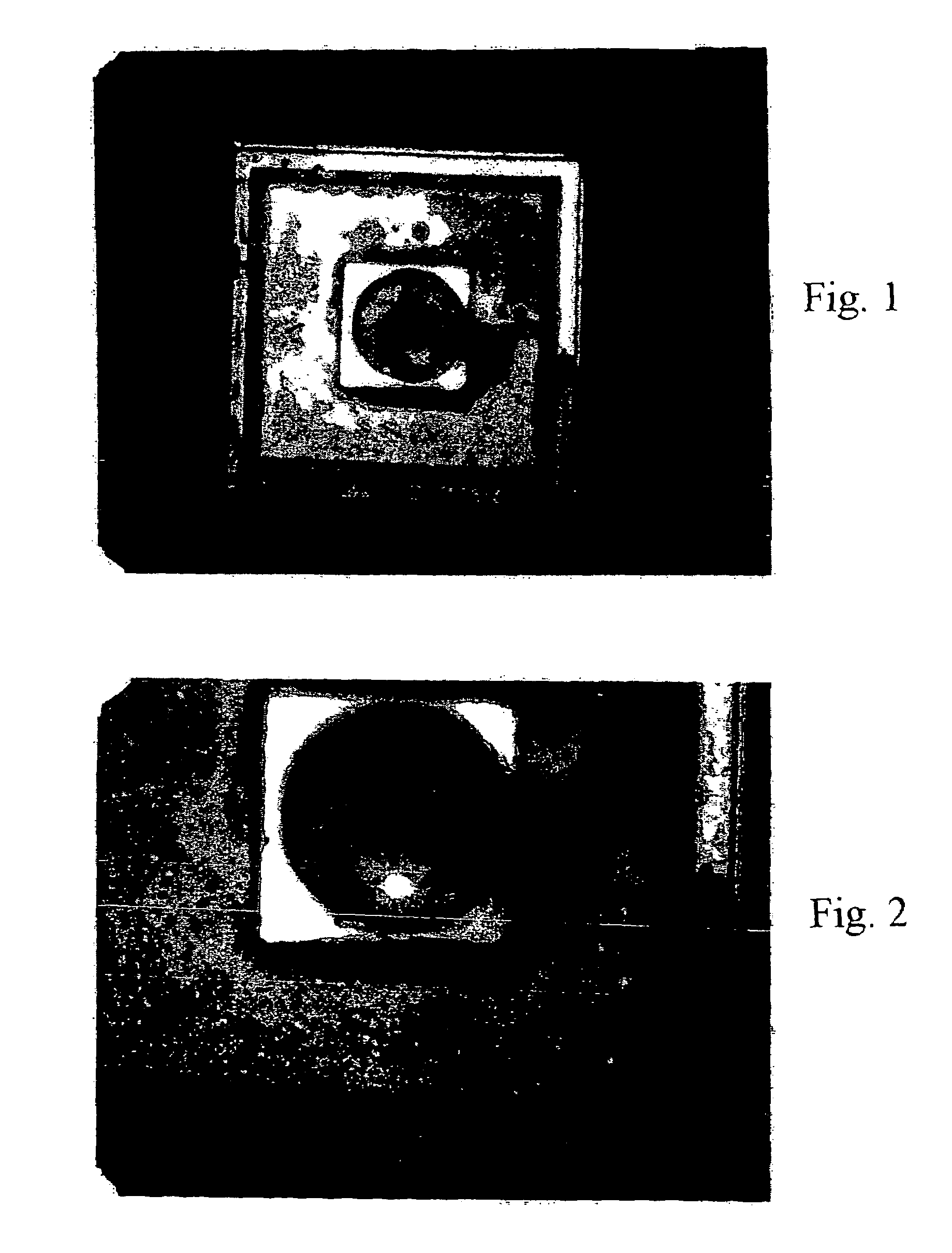
[0036]In this regard, FIG. 1 is a photograph of an entire LED (“die”). In the device of FIG. 1 the passivation layer of silicon dioxide (glass) has been removed except around the outside edge of the die. The portions where glass is still present are generally indicated by the spotted or stained-appearing portions around the perimeter of the generally square die. This mottled appearance results from a varying gap of air under the glass as it delaminates from the die. In the die illustrated in FIG. 1, the delamination begins at about the three o'clock position (moving clockwise) and reaches approximately the 11:00 o'clock p...


PUM


Abstract

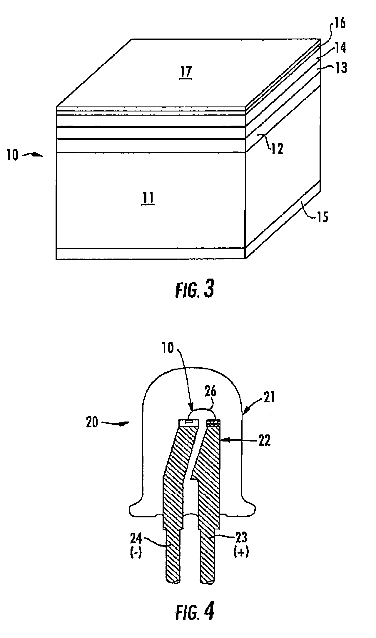
A physically robust light emitting diode is disclosed that offers high-reliability in standard packaging and that will withstand high temperature and high humidity conditions. The diode comprises a Group III nitride heterojunction diode with a p-type Group III nitride contact layer, an ohmic contact to the p-type contact layer, and a sputter-deposited silicon nitride composition passivation layer on the ohmic contact. A method of manufacturing a light emitting diode and an LED lamp incorporating the diode are also disclosed.

Description

CROSS REFERENCE TO RELATED APPLICATION [0001]This application is a divisional of U.S. application Ser. No. 10 / 145,222, filed May 14, 2002, (the '222 application), now U.S. Pat. No. 6,825,501. The '222 application is a continuation-in-part of U.S. application Ser. No. 08 / 920,409, filed Aug. 29, 1997, now abandoned the contents of which are incorporated entirely herein by reference.FIELD OF THE INVENTION[0002]The present invention relates to light emitting diodes and in particular relates to such diodes formed from Group III nitrides suitable for standard packaging applications.BACKGROUND OF THE INVENTION[0003]A light emitting diode is a p-n junction device that converts electrical energy into optical radiation. In particular, under proper forward-biased conditions LED's emit external spontaneous radiation in the ultraviolet, visible, and infra-red regions of the electromagnetic spectrum.[0004]As known to those familiar with the visible and near-visible portions of the electromagnetic...

Claims


Application Information

Patent Timeline
Patent Type & Authority Patents(United States)
IPC IPC(8): H01L21/00H01L21/318H01L33/32H01L33/40H01L33/42H01L33/44
CPCH01L33/44H01L33/42H01L33/40H01L33/32H01L2224/48091H01L2924/00014
Inventor EDMOND, JOHN ADAMTHIBEAULT, BRIANSLATER, JR., DAVID BEARDSLEYNEGLEY, GERALD H.MIECZKOWSKI, VAN ALLEN
Owner CREE INC
Learn More