Power gating techniques able to have data retention and variability immunity properties

a power gating and data retention technology, applied in logic circuits, pulse techniques, reliability increasing modifications, etc., can solve the problems of increasing power dissipation, reducing battery life in mobile systems, expensive packaging and cooling solutions, etc., and achieve the effect of reducing the power consumption of said logic circuits

Active Publication Date: 2006-10-24
GLOBALFOUNDRIES US INC
View PDF6 Cites 40 Cited by
  • Summary
  • Abstract
  • Description
  • Claims
  • Application Information

AI Technical Summary

Benefits of technology

[0015]In an exemplary aspect of the invention, a power gated semiconductor integrated circuit comprises: (1) logic circuit to be power gated, said logic circuit having a virtual ground rail; (2) footer device disposed between said virtual ground rail and a ground rail for reducing power consumption of said logic circuit; and (3) virtual rail voltage clamp disposed electrically in parallel with said footer device for limiting the voltage at the virtual ground rail, the virtual rail voltage clamp comprising at least one NFET.

Problems solved by technology

Increased power dissipation is becoming a major challenge in the design of integrated circuits.
Increased power dissipation causes several problems including reducing battery life in mobile systems, expensive packaging and cooling solutions and can also result in chip failures.
Of the various components contributing to power dissipation, leakage or static power dissipation is growing very fast and is predicted to exceed dynamic power dissipation in the near future.
Even though power gating is very effective in reducing leakage (reduces leakage by 90% or more) and seems like a simple idea, there are many difficulties in implementing power gating.
Note that many of the problems arise because in the power gated state, latches lose their data and the outputs of the logic circuit being power gated assume an unknown state.1. The state of the latches in the power gated logic circuit may need to be stored before turning off the power gating transistors and restored during power-up.2. Since a power gated logic circuit loses its state, fence circuitry is required to interface the power gated logic with neighboring logic which is not power gated.3. Power gating can affect the response time of the circuit negatively.
The penalty may arise since one or more cycles may be required during power gating and power-up to store and restore the state.
This can require significant effort.
One of the issues to be considered is when to turn a unit on or off.
Another complication arises if multiple units are power gated.
In this case, the power management unit has to coordinate the change of state of the multiple units since turning multiple units on or off simultaneously could cause unacceptable noise on the power rails.5. It can be seen from the previous items that power gating adds significant burden on verification—both functional as well at the circuit levels.
However, the modification means that leakage reduction is sacrificed.
Since powergating with VRC prevents state loss, many of the problems associated with powergating without VRC are overcome partially or fully but at the cost of increased leakage.

Method used


Image

  • Power gating techniques able to have data retention and variability immunity properties
  • Power gating techniques able to have data retention and variability immunity properties
  • Power gating techniques able to have data retention and variability immunity properties

Examples


Embodiment Construction

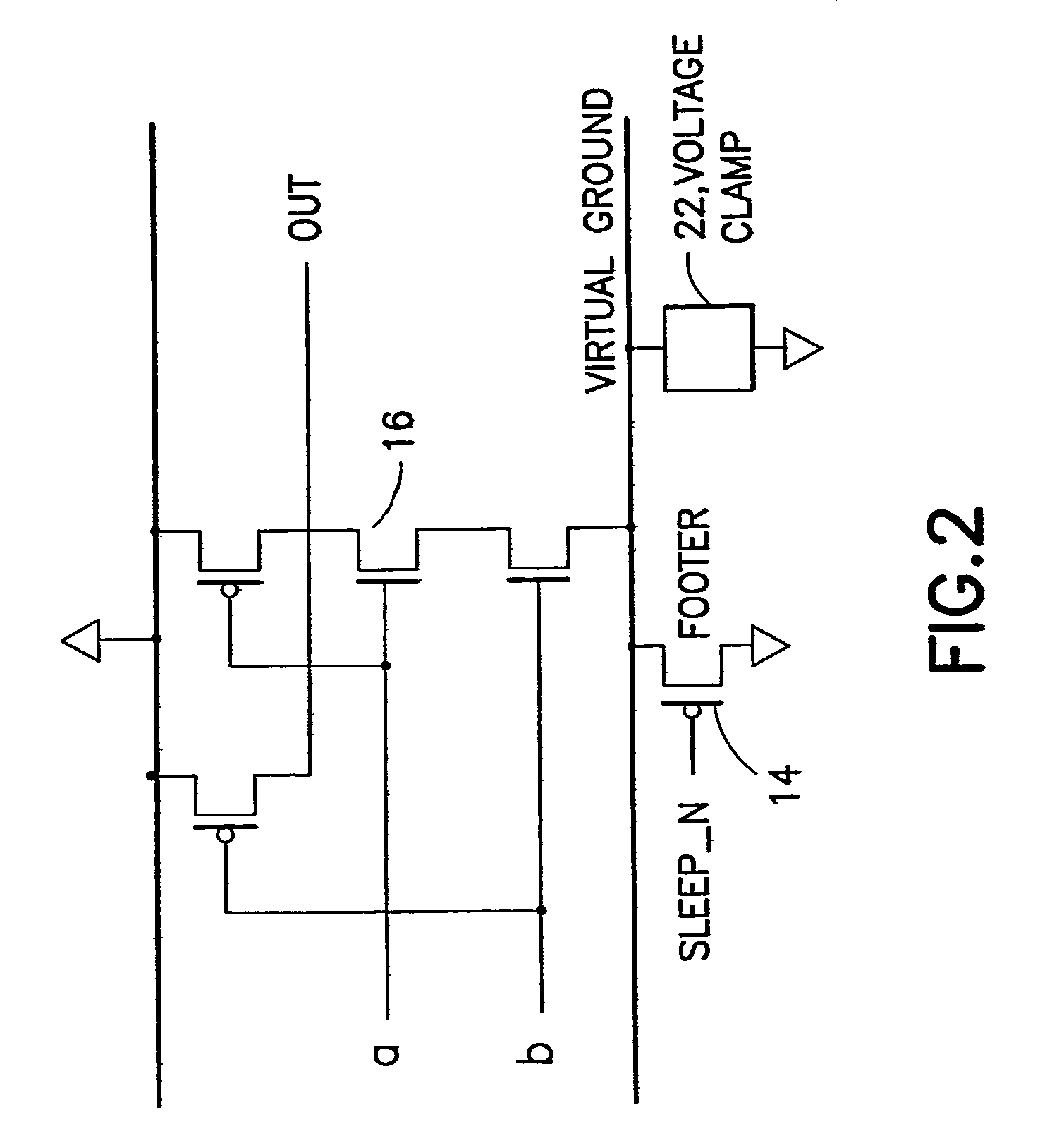
[0028]The present invention, in an exemplary embodiment, uses an NFET as a virtual rail clamp (VRC), such as voltage clamp 22 of FIG. 2, for a footer (e.g., PFET as a VRC for a header). As is described in more detail below, using an NEET as a voltage clamp for a footer seems to be a poor choice. Nonetheless, as the disclosure will show, under the voltage ranges over which voltage clamping needs to be applied, an NFET can also work as a good voltage clamp. Further, the disclosure will show that using a PFET or diode as a VRC requires costly modifications during manufacturing while using an NFET does not require any modifications to manufacturing. In addition, a method is disclosed to make the VRC implementation immune to manufacturing variability, which is becoming the most significant problem facing designers in addition to power with future technologies. The exemplary method for variability immunity can be modified in a manner obvious to those skilled in the art of powergating to b...


PUM


Abstract

A power gated semiconductor integrated circuit comprises: (1) logic circuit to be power gated, said logic circuit having a virtual ground rail; (2) footer device disposed between said virtual ground rail and a ground rail for reducing power consumption of said logic circuit; and (3) virtual rail voltage clamp disposed electrically in parallel with said footer device for limiting the voltage at the virtual ground rail, the virtual rail voltage clamp comprising at least one NFET. A total of Nf NFETs are connected to the virtual ground rail of the integrated circuit for use as both virtual rail voltage clamps and footer devices. A quantity of Nmax-VC NFETs are scanned and perform the function of voltage clamps and the remaining (Nf−Nmax-VC) NFETs perform power gating. Manufacturing variability immunity and tuning of the variability immunity is achieved by adjusting the quantity Nmax-VC based upon testing of the manufactured integrated circuit.

Description

BACKGROUND OF THE INVENTION[0001]The present invention relates, in general, to semiconductor integrated circuits, and, more specifically, to a semiconductor integrated circuit and methods therefore capable of reducing leakage current and hence, power consumption by controlling the supply of power for an internal logic circuit in accordance with active state and sleep state of the internal circuit.[0002]Increased power dissipation is becoming a major challenge in the design of integrated circuits. Increased power dissipation causes several problems including reducing battery life in mobile systems, expensive packaging and cooling solutions and can also result in chip failures. Of the various components contributing to power dissipation, leakage or static power dissipation is growing very fast and is predicted to exceed dynamic power dissipation in the near future.[0003]Much effort has gone into investigating methods for reducing and controlling leakage in circuits. The multi-Vth tech...

Claims


Application Information

Patent Timeline
Patent Type & Authority Patents(United States)
IPC IPC(8): H03K19/003
CPCH03K19/0008H03K19/0016
Inventor BHATTACHARYA, SUBHRAJIT
Owner GLOBALFOUNDRIES US INC
Why Eureka
Try Eureka