Method and device for generating a clock signal with predetermined clock signal properties

a clock signal and predetermined clock signal technology, applied in the direction of generating/distributing signals, pulse techniques, instruments, etc., can solve the problems of high jitter contribution, high clock accuracy, and low clock signal quality, and achieve optimal performance, high degree of reusability results, and improved performance

Active Publication Date: 2006-10-24
AVAGO TECH INT SALES PTE LTD
View PDF17 Cites 11 Cited by
  • Summary
  • Abstract
  • Description
  • Claims
  • Application Information

AI Technical Summary

Benefits of technology

[0024]According to a further advantage of the present invention, possible implementations of the technology are active in modular construction, wherein using a set of simple, standardized modules for the digital clock synthesis almost any application may be served, whereby a very high degree of reusability results.
[0034]Design flexibility of the circuit: the synthesis of a certain clock signal may be designed very flexible in hardware and later exact clock properties for an optimal performance or for avoiding errors may be adjusted.
[0035]A further advantage of the digital clock signal synthesis is, that with every improvement or with every new digital technology an improved performance and an improved accuracy is obtained by the digital clock signal synthesis. The main parameter in the digital clock signal synthesis is to improve the phase accuracy of the multi-phase clock signal.
[0036]After all clock signal parameters in the digital domain are manipulated, it is thus active to adjust a clock signal to fixed requirements in a very flexible way. Many new applications will take advantages from this property, for example the precise delaying of signals by clocking with a shiftable clock in the phase.
[0037]Further, it is also possible to generate clock signals having higher frequencies than the master clock signal using a multi-phase clock signal having a short clock cycle, as based on the primary edges additional clock edges having the same cycle maybe calculated in a simple way. Shorter multi-phase clock signals may be derived by a logic combination of two phases. The shortest possible high period of the multi-phase clock signal is twice the phase accuracy.

Problems solved by technology

Such traditional approaches are disadvantageous, as here the overall jitter contribution is high and the clock accuracy is limited, as conventional analog PLLs are limited to discrete frequencies which are admitted by the PLL divider elements.
A further disadvantage of conventional approaches is, that the analog circuits used require a plurality of circuit blocks, so that the circuit complexity is high.
Further, the number of PLLs that may be realized on a single chip is limited, and thus also the number of available independent clock signals.
Again, a further disadvantage of conventional approaches is, that for each of the PLLs used with conventional analog approaches an associated external analog power supply must be provided.
The design expense for analog circuits is high.
It is not possible to generate (several) clocks with a binary programmable frequency, duty cycle and phase with any accuracy (not even integer) multiples of a sync clock.

Method used


Image

  • Method and device for generating a clock signal with predetermined clock signal properties
  • Method and device for generating a clock signal with predetermined clock signal properties
  • Method and device for generating a clock signal with predetermined clock signal properties

Examples


Embodiment Construction

[0062]In the following, preferred embodiments are described in more detail with reference to the accompanying drawings, wherein in the description of the individual drawings similar or like elements are designated with the same reference numerals.

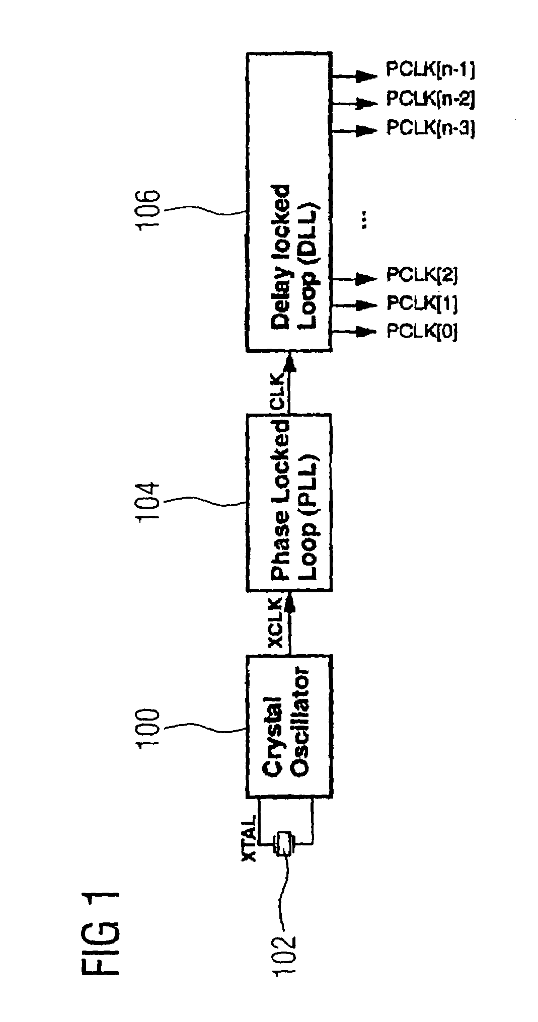
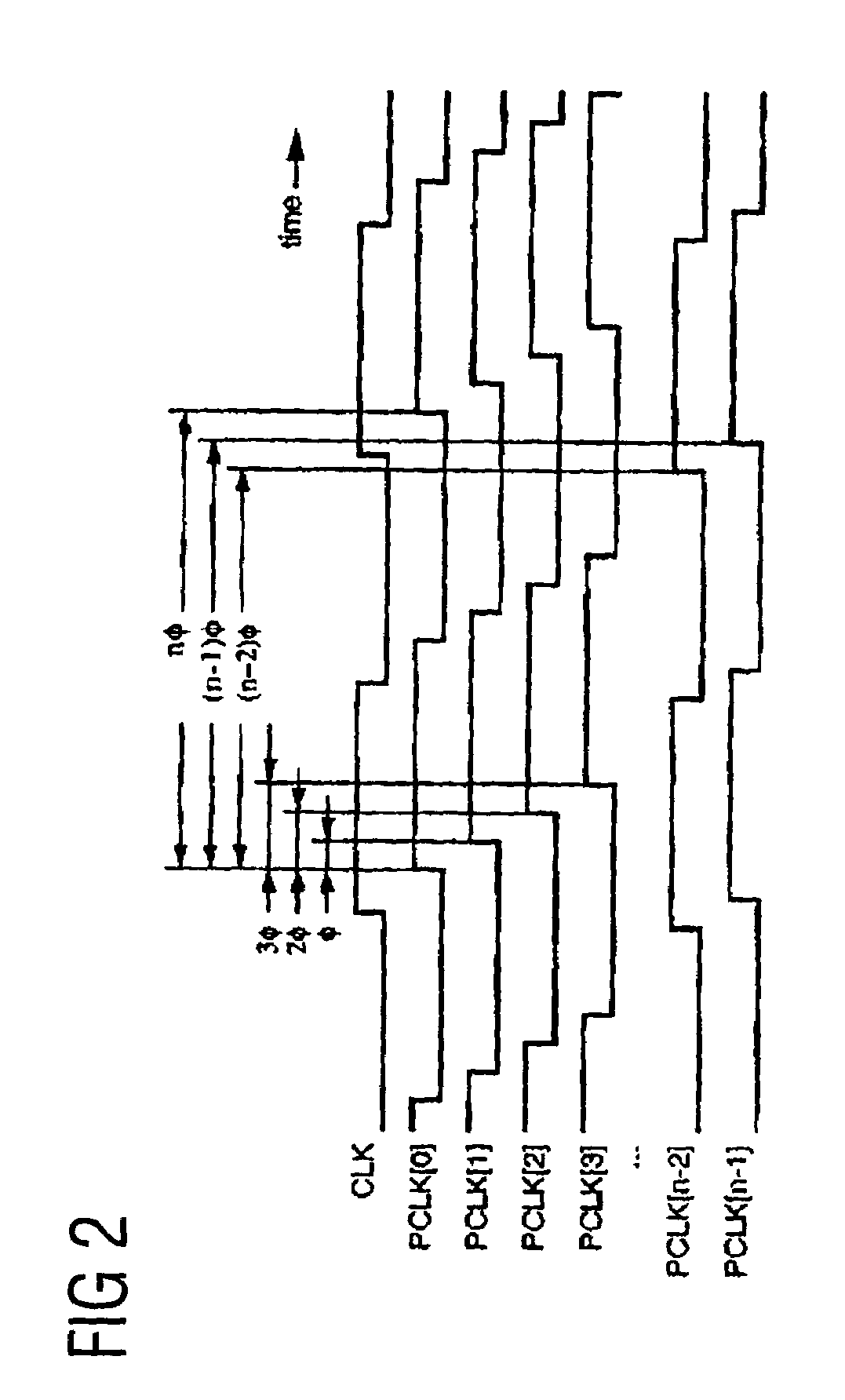
[0063]FIG. 1 shows an example for a multi-phase clock oscillator, which includes a crystal oscillator 100 which is coupled to an oscillating crystal 102 in order to output an oscillator clock signal XCLK. The oscillator clock signal XCLK is received by a phase locked loop (PLL) 104, which generates a master clock signal CLK based on the received oscillator clock signal, which is provided to the delay locked loop (DLL). The DLL 106 generates a plurality of clock signals PCLK[0] . . . PCKL[n−1] on the basis of the applied master clock signal CLK. The generated clock signals all have the same frequency, comprise however respectively different phase relations in contrast to the master clock signal CLK and thus also comprise different phase rela...


PUM


Abstract

A method and device for generating a clock signal with predetermined clock signal properties firstly prepare a number of clock signals with an essentially identical frequency and with a respectively different phase relation with regard to a master clock signal in order to subsequently (on the basis of a control signal, which is prepared according to the clock signal to be generated), select predetermined clock signals from the number of prepared clock signals and to combine the selected clock signals in order to generate the desired clock signal.

Description

CROSS-REFERENCE TO RELATED APPLICATION[0001]This application is a continuation of copending International Application No. PCT / EP03 / 11558, filed Oct. 17, 2003, which designated the United States and was not published in English.BACKGROUND OF THE INVENTION[0002]1. Field of the Invention[0003]The present invention relates to a system for a digital synthesis of several different clock signals (DCS=digital clock synthesis), and in particular to a method and a device for generating a clock signal having predetermined clock signal properties, and here in particular to a method and to a device for generating a clock signal with almost any desired frequency and a desired duty cycle.[0004]2. Description of the Related Art[0005]Traditionally, independent clock signals are generated using the known analog clock synthesis, wherein conventionally a plurality of PLLs (PLL=phase locked loop) are used. Such traditional approaches are disadvantageous, as here the overall jitter contribution is high a...

Claims


Application Information

Patent Timeline
Patent Type & Authority Patents(United States)
IPC IPC(8): G06F1/04G06F1/08G06F7/68H03K5/135H03L7/06H03L7/081H03L7/16H03L7/22
CPCG06F1/08G06F7/68H03L7/22H03L7/0812H03K5/135
Inventor FURTNER, WOLFGANG
Owner AVAGO TECH INT SALES PTE LTD
Why Eureka
Try Eureka