Clock recovery circuit with second order digital filter

a recovery circuit and digital filter technology, applied in the direction of digital transmission, pulse automatic control, code conversion, etc., can solve the problems of increasing the probability of injection locking and a significant amount of surface area on the circuit board, and achieve the effect of high speed and increased performance of the integrated circui

Active Publication Date: 2006-10-24
CADENCE DESIGN SYST INC
View PDF34 Cites 34 Cited by
  • Summary
  • Abstract
  • Description
  • Claims
  • Application Information

AI Technical Summary

Benefits of technology

[0002]One approach to performing the clock recovery is to use an analog voltage controlled oscillator (VCO) in a phase locked loop (PLL) to generate the recovered clock. In the case of multiple data streams, a disadvantage of this approach is that a VCO and a PLL is required for each input, which may consume a significant amount of area on a circuit board. Further, multiple VCOs on an IC may also increase the probability of injection locking where the VCOs will lock together.

Problems solved by technology

In the case of multiple data streams, a disadvantage of this approach is that a VCO and a PLL is required for each input, which may consume a significant amount of area on a circuit board.
Further, multiple VCOs on an IC may also increase the probability of injection locking where the VCOs will lock together.

Method used


Image

  • Clock recovery circuit with second order digital filter
  • Clock recovery circuit with second order digital filter
  • Clock recovery circuit with second order digital filter

Examples


Embodiment Construction

[0018]The present invention is disclosed in a number of embodiments as methods and mechanisms for recovering the data of a serial data stream. Some of the embodiments described are directed to digital clock recovery filters. However, the principles presented here are applicable to any type of clock recovery filter, such as analog clock recovery filters, and thus the scope of the invention is not to be limited to the exact embodiments shown herein.

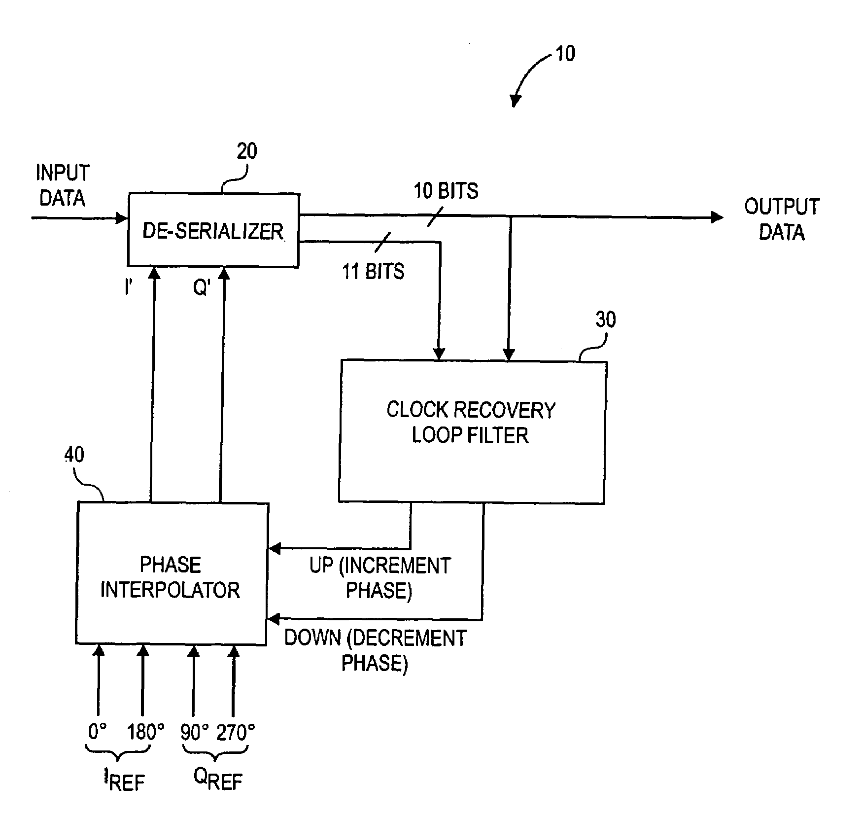
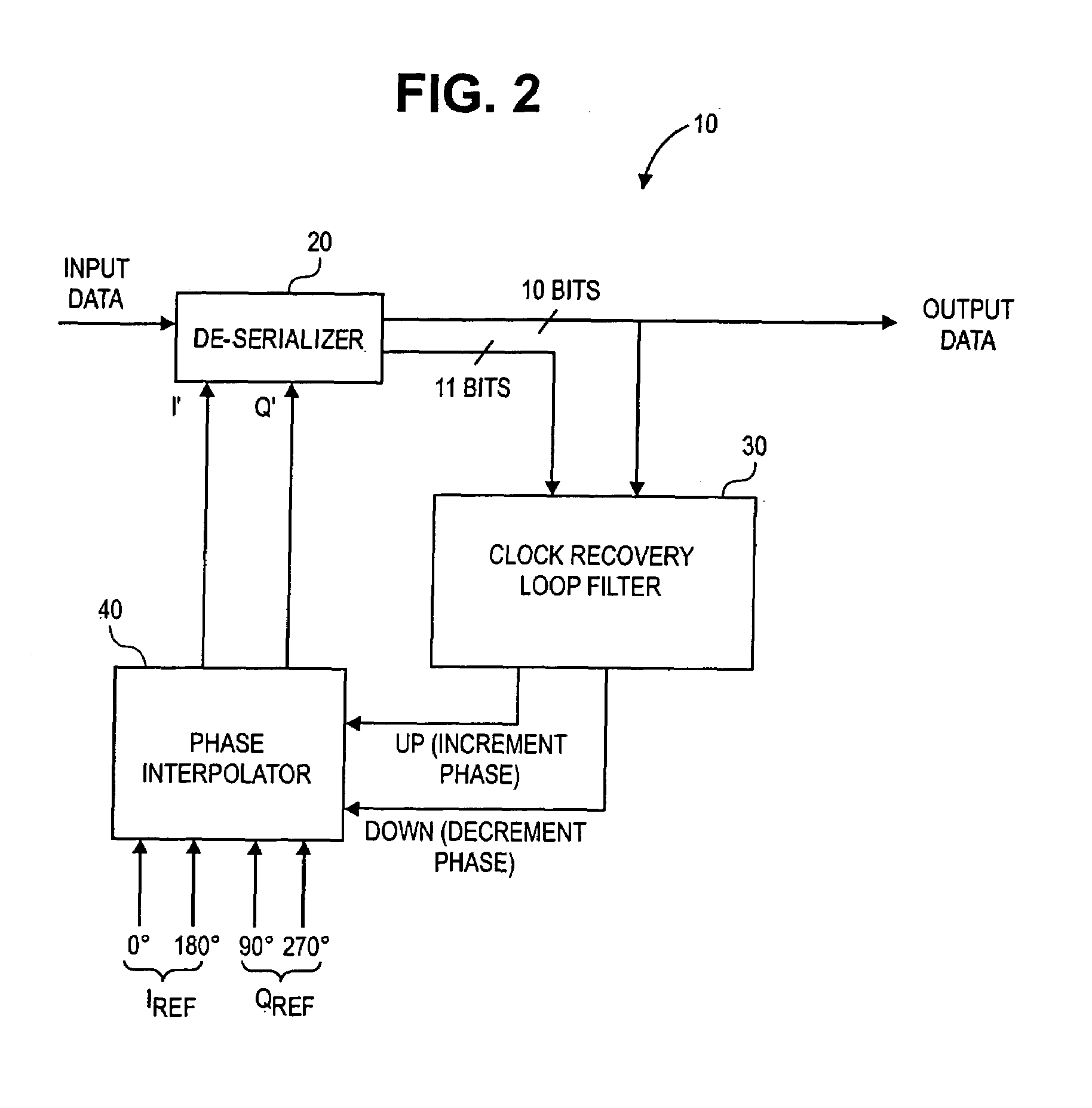
[0019]As described above, in order to recover data from a serial bit data stream, the data stream may need to be reclocked. A clock recovery circuit can be used by an IC to reclock the data stream and recover the data. Turning to FIG. 2, a clock recovery circuit 10 in accordance with an embodiment of the present invention is shown. The circuit 10 includes a de-serializer 20, which receives serial input data, reclocks the data, and generates a corresponding de-serialized output data. The de-serializer 20 is coupled with a clock recovery loop...


PUM


Abstract

The present invention provides a method and mechanism for regenerating the clock signal and recovering the data of a serial bit data stream. According to an embodiment, a circuit for recovering data from a serial bit stream may include a de-serializer configured for reclocking the serial bit stream using at least one reclocking signal, having a frequency with a phase, and de-serializing the serial bit stream into at least two bit streams. The circuit may further include a clock recovery loop filter having a second order filter coupled with the deserializer. The clock recovery loop filter may be configured for determining whether the de-serializer is reclocking the serial bit data stream at an optimum location and for generating at least one control signal to adjust the phase of the frequency of the at least one reclocking signal if the de-serializer is not reclocking the serial bit data stream at the optimum location. The circuit may also include a phase interpolator coupled with the clock recovery loop filter and the de-serializer, configured for generating the at least one reclocking signal in accordance with the at least one control signal.

Description

BACKGROUND AND SUMMARY[0001]As the performance of integrated circuits (ICs) increases, so does the amount of data transferred between ICs. The industry trend has been to transfer the data serially at very high speeds, e.g., transfer rates in excess of 1 Gigabit / second. Generally, when transferring data serially at these high speeds from a first IC to a second IC, the clock data needed to reclock the serial bit stream at the second IC is not included with the data being transferred. One approach to recover the data from the serial bit stream is to include circuitry on the second IC to regenerate the clock and recover the data. This circuitry is often referred to as a “clock recovery circuit.” Turning to FIG. 1, the serial bit stream of data, i.e., 1's and 0's, is generally comprised of a sinusoidal type signal 3. If the signal 3 is overlapped onto itself, an “eye” shape 7 is formed. Generally, the optimum point within the signal 3 to determine whether the data is a 1 or a 0 with the ...

Claims


Application Information

Patent Timeline
Patent Type & Authority Patents(United States)
IPC IPC(8): H04L7/00
CPCH03L7/0814H03L7/091H03L7/093H03M9/00H04L7/033H03L7/0998H04L7/0025H04L7/0083
Inventor EVANS, WILLIAM P.GRAY, C. THOMASHUSS, SCOTT
Owner CADENCE DESIGN SYST INC
Why Eureka
Try Eureka