

Enhanced forward link power control during soft hand-off
- Summary
- Abstract
- Description
- Claims
- Application Information
AI Technical Summary
Benefits of technology
Problems solved by technology
Method used
Image

Examples
Embodiment Construction
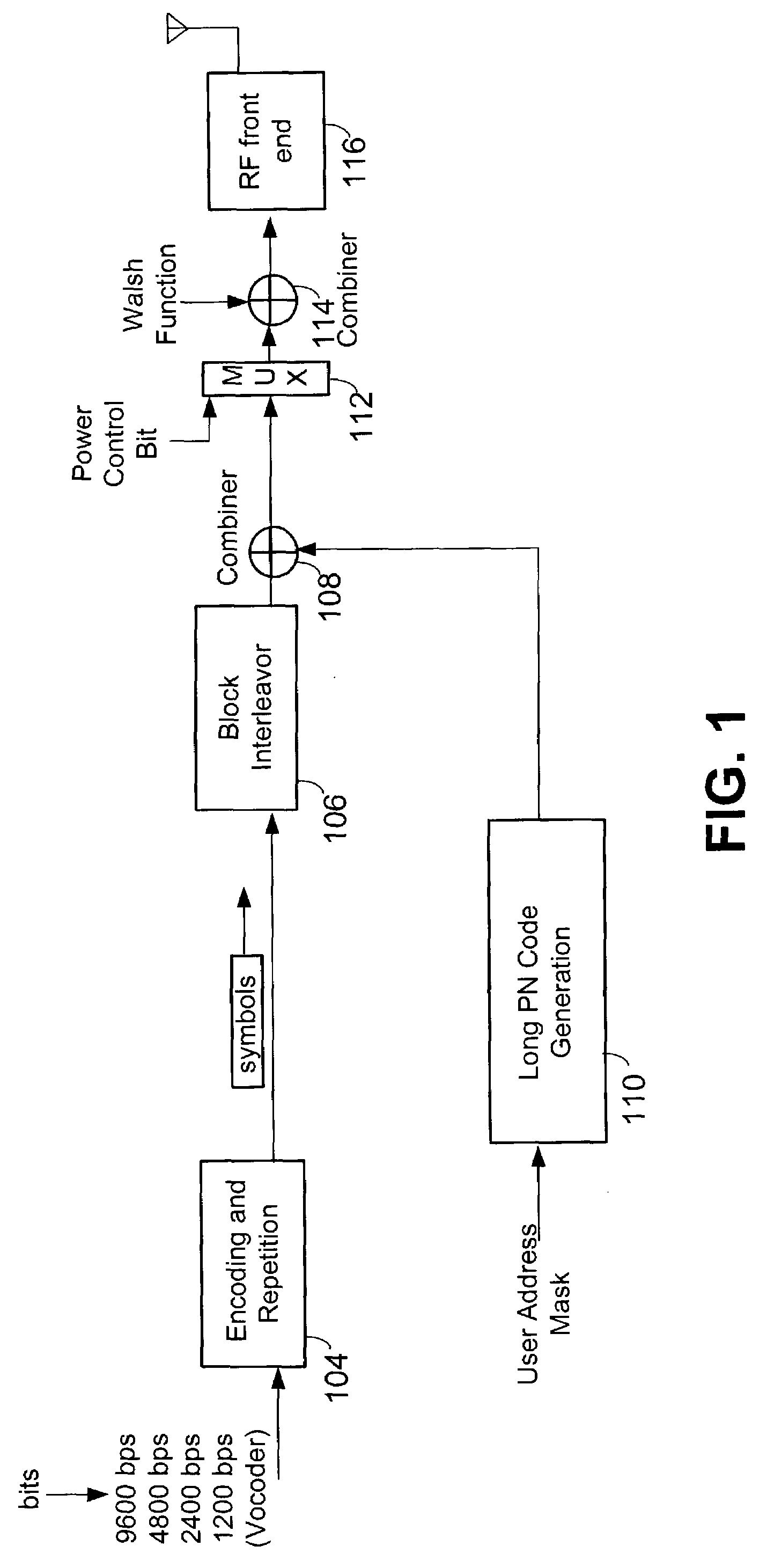
[0018]FIG. 1 illustrates a typical CDMA transmitter system for use on a forward link from a base station transceiver subsystem (BTS) to a CDMA mobile station. An encoder 104 creates a digital baseband signal by encoding a digitized signal representing an analog voice or digital data service. Encoder 104 accepts data bits in, and produces code symbols at, an output. For each clock cycle, a new data bit is shifted into a register of encoder 104 and the data bit previously received is output. The various inputs of encoder 104 are added (modulo 2) in a predetermined fashion to produce two or more symbols out for each clock cycle. Since the new symbols generated for each clock cycle are derived from the values of the new bit being input in all current data bits occupying the shift register during a given interval, a certain level of predictability can be realized. The output symbols of encoder 104 are then produced to a block interleaver 106. Block interleaver 106 serves to create a matr...
PUM
 Abstract
Description
Claims
Application Information