
Removable conformal liners for centrifuge containers

Inactive Publication Date: 2006-10-31
BECKMAN COULTER INC
View PDF11 Cites 3 Cited by
  • Summary
  • Abstract
  • Description
  • Claims
  • Application Information

AI Technical Summary

Benefits of technology

[0007]It is an object of the present invention to develop a cost-efficient, rapid and convenient method for the separation of the solids from suspensions by centrifugation. Particularly, it is an object of the present invention to develop a centrifuge container assembly that minimizes the time required for its cleaning, reduces direct exposure of a technician to hazardous pellets and, at the same time, increases the efficiency of the pellet harvesting. It is also an object of the present invention to develop a centrifuge container assembly that provides a sample-tight seal and prevents sample spilling during centrifugation.
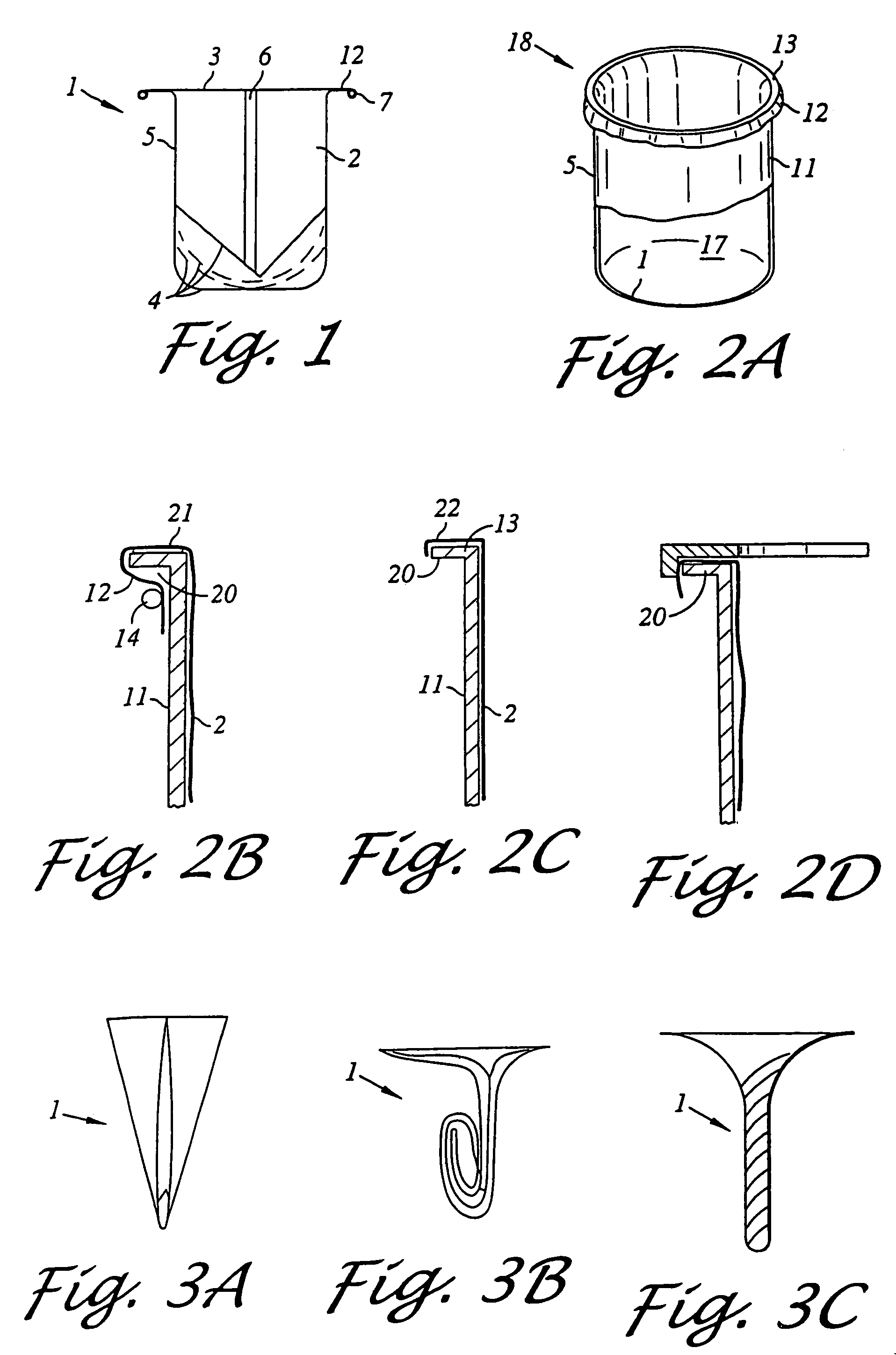
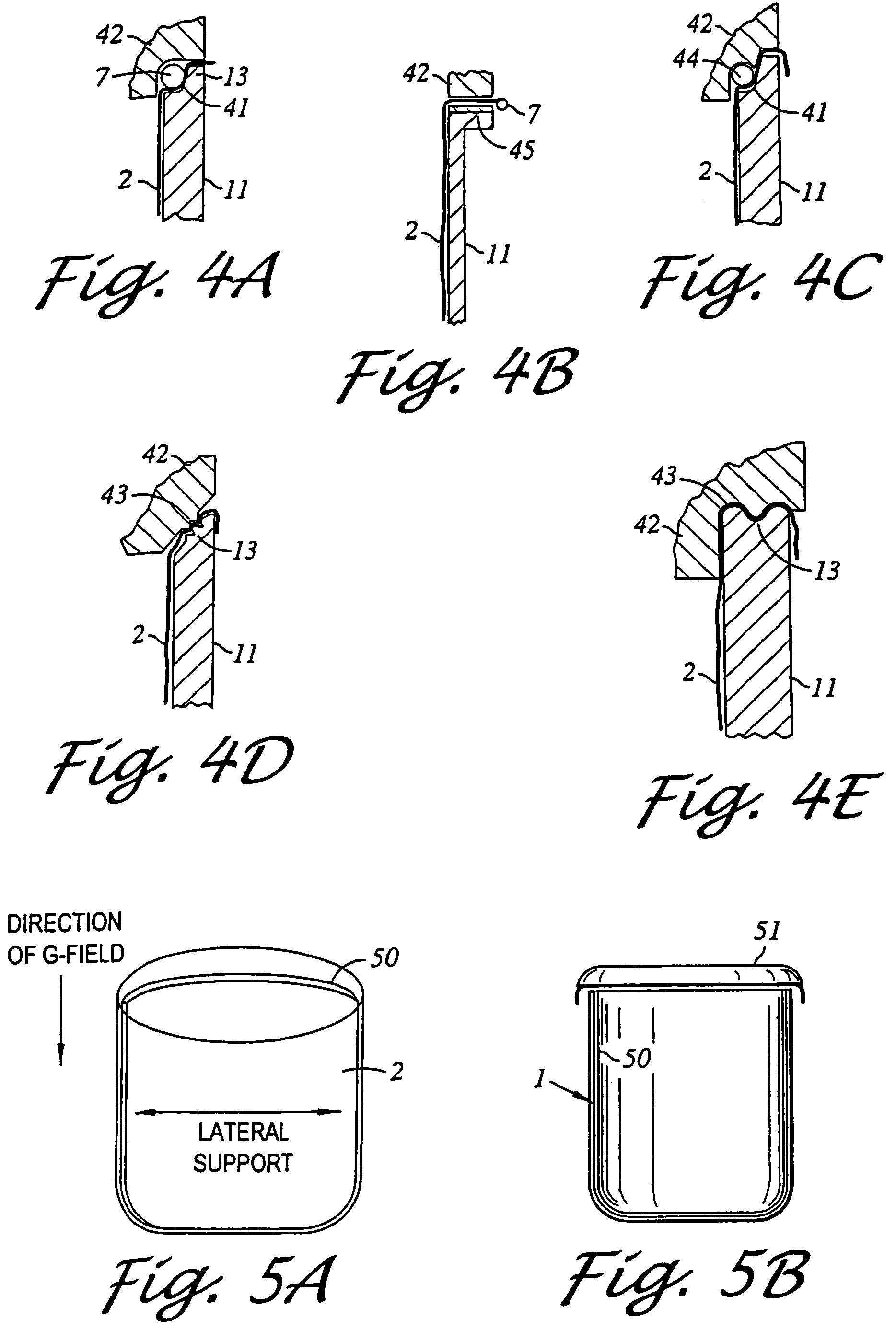
[0009]In another aspect, the present invention provides a removable centrifuge container assembly. The assembly includes a centrifuge container with an interior cavity and an opening, and a removable liner with a flexible or semi-rigid body placed in the container. In one embodiment, the liner body is made of a sufficiently resilient material, which allows a reversible deformation of the liner body. This embodiment is particularly advantageous for use with containers which have a narrow neck. When the liner body is made of a resilient material, it may be deformed in such a way that its dimension is sufficiently reduced so that it can fit through the neck of the container. Once released inside the container, the liner unfolds to allow placement of a sample. The centrifuge container assembly of this invention may also have a retaining-means for retaining the liner in a fixed position within the container. The retaining-means may comprise a first mating element formed on the liner body and a second mating element formed on the container. The first and the second mating elements are capable of engaging each other in order to secure the liner. Alternatively, a top portion of the liner may be draped over the edge of the container opening and secured with a retaining-means, such as a tie wrap or a resilient member.
[0011]The present invention has been found to provide a number of advantages. The centrifuge container assembly can be used to recover the solids from a broad range of suspensions, which includes, but is not limited to, biological materials, such as cell lysates, blood, urine and culture media, and industrial fluids, such as waste washout liquids and sludge. The invention is particularly advantageous in applications dealing with the recovery of the solids from the diluted samples and in applications where limiting direct exposure of a technician to hazardous pelleted solids is desirable.
[0013]The liners of this invention can be made disposable, which eliminates the need for the mechanical cleaning of the centrifuge containers and reduces exposure of a technician to hazardous solid materials. The use of such disposable liners also permits the centrifuge containers to be used with the increasing numbers of suspensions, as the difficulties previously encountered in cleaning the containers of certain pelleted solids become obviated when all that is necessary is to dispose of the liner. For additional convenience, the disposable liners can be sterilized to accommodate the aseptic sample processing or fabricated in a defined particle, clean environment. The liners can be made of a material that is resistant to gamma, E-beam, and ETO sterilizing techniques. The liners may also be made of materials that are puncturable, resistant to freeze-thaw cycles, clear, chemically resistant, or have other properties useful in particular applications. A disposable and sterile liner of the present invention provides an inexpensive and convenient method for the improved recovery of the solids by centrifugation, which makes mechanical cleaning and sterilization of the centrifuge containers unnecessary. Finally, the liners of this invention assist in creating a sample-tight seal between a centrifuge container and a closure, thus preventing the sample from leaking during centrifugation.

Problems solved by technology

The existing designs of centrifuge containers, however, do not offer an easy access to pellets for their harvesting or disposal.
In applications dealing with diluted suspensions, complete harvesting of a pellet can be particularly difficult.
In some applications, sample containers have to be cut to retrieve a pellet, which is not always an economically feasible option.
Also, existing centrifuge containers cannot accommodate applications where the pellet is a hazardous material (e.g., a biohazard) and a minimal direct handling of the pellet by a technician is desirable.
Furthermore, cleaning of the centrifuge containers from the solids remaining on the walls after the pellet is harvested requires laborious and tedious scrubbing and washing.
The difficulty of thorough cleaning of the centrifuge container further increases as the dimensions of the neck opening of the container decreases.
That is, whereas some types of solid residue may be easily cleaned from wide-mouthed bottles, such residue becomes more difficult to remove where the bottle is of narrow-mouthed construction.
However, the mechanical strength of the materials does not always correspond to their chemical and physical resistance.
Consequently, certain chemically aggressive materials cannot be processed in conventional centrifuge containers or require bulky and expensive designs.
Finally, when an aseptic procedure is called for, the centrifuge containers have to be sterilized, which often takes 30–60 minutes.
This relatively long preparation time of a conventional centrifuge container further decreases efficiency of the sample processing.
The conventional centrifuge container designs, therefore, fail to provide convenient methods for the separation of solids by centrifugation with little or no time required for cleaning and sterilization of the containers prior to the next centrifugal cycle.
The conventional designs are also limited to only certain types of samples that can be processed.

Method used


Image

  • Removable conformal liners for centrifuge containers
  • Removable conformal liners for centrifuge containers
  • Removable conformal liners for centrifuge containers

Examples


Embodiment Construction

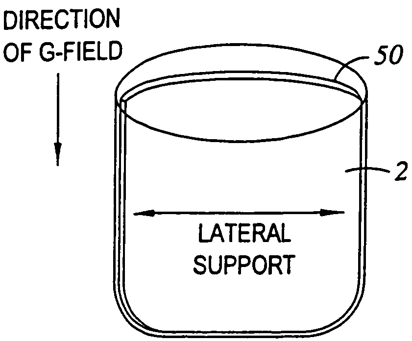
[0028]Referring to FIGS. 1 and 2A, a removable liner 1 for a centrifuge container embodying the present invention comprises a flexibie or semi-rigid body 2 with an opening 3 for introducing a sample. As shown in FIG. 2A, once the liner of this invention is inserted into a centrifuge container 11, the liner-body conforms to the interior shape of the container.

[0029]For the purpose of this invention, a flexible or a semi-rigid liner body is made of any material that allows a deformation of the liner body without breakage. The semi-rigid liner body of this invention is a freestanding structure that can maintain its 3-D shape outside of the container, both when empty and when filled with a sample. The flexible liner body, on the other hand, cannot support the weight of a sample on its own outside of the container. Both semi-rigid and flexible liner bodies can be made of a wide range of materials, including, but not limited to, paper, carton, polyethylene, polyvinylchloride (PVC), ethyl ...


PUM

PropertyMeasurementUnit
Strengthaaaaaaaaaa

Abstract

A removable conformal liner for a centrifuge container is described. The liner has a flexible or semi-rigid body with an opening for introducing a sample. When the liner is inserted into an internal cavity of a centrifuge container, the body of the liner conforms to the interior cavity. The liner body may be made of a material that is sufficiently resilient to allow a reversible deformation of the body by folding, twisting, collapsing, rolling, or pleating.

Description

[0001]This is a continuation application of U.S. application Ser. No. 10 / 213,018, filed on Aug. 5, 2002, now U.S. Pat. No. 6,746,601, which is a divisional application of Ser. No. 09 / 607,232 filed Jun. 30, 2000, now U.S. Pat. No. 6,458,067, the content of which is incorporated herein in its entirety by references.AREA OF THE ART[0002]The invention relates to removable liners for centrifuge containers and a method of using such liners for separating solids from suspensions by centrifugation.DESCRIPTION OF THE PRIOR ART[0003]Centrifugation is a widely used method for separating solid and liquid phases of suspensions. The solid phase is more dense than the liquid phase, and during centrifugation, solids settle at the bottom of the centrifuge container, forming a dense pellet. The lighter liquid phase forms a top layer, also called a supernatant. At the end of centrifugation, the supernatant can be decanted and the pellet harvested or discarded. The initial separation step may be follow...

Claims


Application Information

Patent Timeline
IPC IPC(8): B04B7/12B65D25/14B01D17/038G01N1/10B01L3/14B04B5/02
CPCB01L3/5021
Inventor DORIN, MELVINMOORE, PATRICK Q.
Owner BECKMAN COULTER INC
Learn More