Bias circuit for smart power amplifier

a power amplifier and smart technology, applied in the direction of amplification control details, transmission, gain control, etc., can solve the problems of short maximum call duration of potable terminals, poor speech quality of services, and restrictions that need to be improved, so as to improve the efficiency of power amplifiers at low power. the effect of reducing the variation of gain power

Active Publication Date: 2006-10-31
DIALOG SEMICON KOREA INC
View PDF4 Cites 22 Cited by
  • Summary
  • Abstract
  • Description
  • Claims
  • Application Information

AI Technical Summary

Benefits of technology

[0021]According to the present invention, when one of the bias circuits operates, the other does not operate. Therefore, the bias circuits in the high power mode and the low power mode may be divided and optimized according to the power. As a result, a gain variation in the power is reduced and the low power mode can be controlled with a small amount of current under a condition of an initial current with low power or a middle power, such that an efficiency of the power amplifier at the low power can be improved.

Problems solved by technology

However, many users have recognized various restrictions of conventional wireless communication services, and those restrictions need to be improved.
Representative problems include short maximum call duration of the potable terminal and bad speech quality of the service.
The batteries that are commonly used are relatively small and light, and can be used for a relatively long time compared to the conventional batteries.
However, performance of the batteries does not yet satisfy the user's needs and expectations.
This is because a power amplifier module of the communication terminal has a low efficiency.
A power consumption of the power amplifier module occupies much of (about 50˜70%) the power consumption of the entire system, such that the low efficiency of the power amplifier module degrades the efficiency of the entire system and largely contributes to shorten the maximum call duration.
As a result, various parts for controlling gains according to the output of the power amplifier may not operate normally.
This reduction of the gain flatness makes it difficult to set the initial current smaller when the low power mode is designed.
This is an unavoidable problem due to the characteristics of the CLASS AB power amplifier requiring more current as the input power increases, and a feedback current should be controlled to effectively suppress the increase of the current.
However, the conventional mode change bias circuit uses a single bias circuit, such that an amount of the feedback current is not controlled differently between the lower mode and high power mode because the identical bias circuit is used in the low power mode and the high power mode.

Method used


Image

  • Bias circuit for smart power amplifier
  • Bias circuit for smart power amplifier
  • Bias circuit for smart power amplifier

Examples


Embodiment Construction

[0026]The present invention will be described more fully hereinafter with reference to the accompanying drawings, in which exemplary embodiments of the invention are shown. This invention may, however, be embodied in different forms and should not be constructed as limited to the embodiments set forth herein. Rather, these embodiments are provided so that this disclosure will be thorough and complete, and will fully convey the scope of the invention to those skilled in the art.

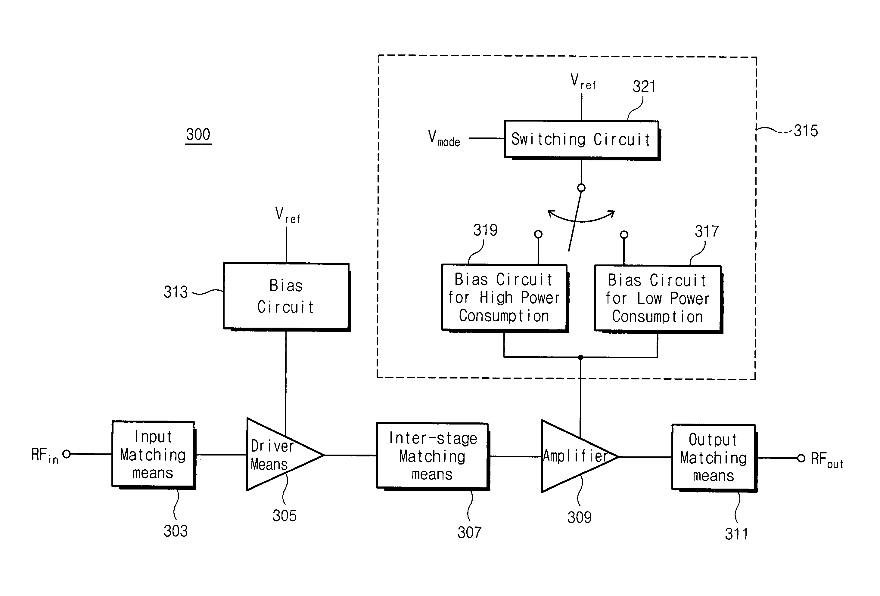
[0027]FIG. 3 is a schematic block diagram illustrating a power amplifier module 300 according to one embodiment of the present invention, and FIG. 4 is a circuit diagram illustrating a double mode bias circuit 315 comprising the module of a power amplifier of FIG. 3.

[0028]Referring to FIG. 3, the module 300 of the power amplifier according to the present invention includes an input matching means 303 connected to an input terminal RFin of a high-frequency signal, a driving stage 305 connected to the input matc...


PUM


Abstract

A bias circuit for a smart power amplifier includes a high power mode bias circuit and a low power mode bias circuit, and operates only one of the bias circuits selectively using a switching circuit according to an input signal. Therefore, the bias circuit of high power mode and the bias circuit of the low power mode are divided and can be optimized according to characteristics of the power. Accordingly, a gain difference with respect to each power can be minimized and the low power mode can be controlled with a small amount of current in a state of initial current with a low power and in a middle power, such that an efficiency of the power amplifier can be improved at low power.

Description

FIELD OF THE INVENTION[0001]The present invention generally relates to bias circuits and more specifically to bias circuits for smart switching mode power amplifiers.BACKGROUND OF THE INVENTION[0002]Recently, explosive developments in wireless communications have paved the way for communicating data through a portable terminal without limitations of time and place. However, many users have recognized various restrictions of conventional wireless communication services, and those restrictions need to be improved. Representative problems include short maximum call duration of the potable terminal and bad speech quality of the service. The maximum call duration of the portable terminal largely relates to a capacity of battery used in the portable terminal. The batteries that are commonly used are relatively small and light, and can be used for a relatively long time compared to the conventional batteries. However, performance of the batteries does not yet satisfy the user's needs and e...

Claims


Application Information

Patent Timeline
Patent Type & Authority Patents(United States)
IPC IPC(8): H03F3/04H04B1/40H03F1/02H03F1/30
CPCH03F1/025H03F1/302H03G1/00H04B1/40
Inventor KIM, TAE-JINLEE, SEUNG-WOOKKIM, BYOUNG-SOOKIM, YONG-WOOKIM, YOUNG-WOONGSHIN, JIN-HO
Owner DIALOG SEMICON KOREA INC
Why Eureka
Try Eureka