Oscillator circuit having stable frequency

a technology of oscillator circuit and stable frequency, which is applied in the direction of oscillator generator, logic circuit pulse generation, pulse technique, etc., can solve the problems of inevitable augmentation of manufacturing cost and associated cost, and achieve simple circuit design and improved temperature dependency

Active Publication Date: 2006-10-31
DENSO CORP
View PDF12 Cites 31 Cited by
  • Summary
  • Abstract
  • Description
  • Claims
  • Application Information

AI Technical Summary

Benefits of technology

[0011]The present invention has been made in view of the above circumstances and has an object to overcome the above problems and to provide an ...

Problems solved by technology

However the materials and implementation of such external parts will result in an inevitable augmentation of manufacturing cost.
Howev...

Method used


Image

  • Oscillator circuit having stable frequency
  • Oscillator circuit having stable frequency
  • Oscillator circuit having stable frequency

Examples


first embodiment

[First Embodiment]

[0038]A first preferred embodiment, which embodies the present invention, will be described herein below in greater details with reference to accompanying drawings.

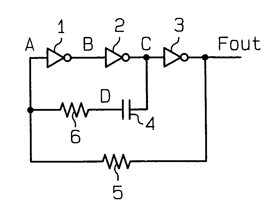
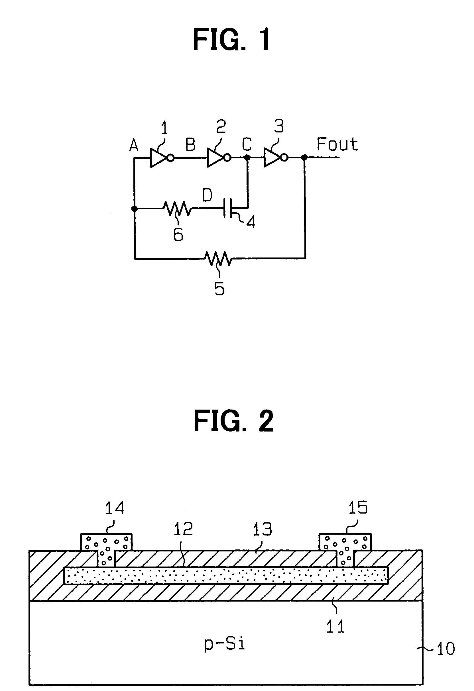
[0039]Referring to FIG. 1, a schematic diagram of an oscillator circuit in accordance with a first preferred embodiment of the present invention is shown. The oscillator circuit in accordance with the preferred embodiment is preferably embodied within a single integrated circuit. The oscillator circuit includes inverters 1, 2, and 3 connected in series. Between the output of the inverter 2 and the input of the inverter 1, a capacitor 4 and a resistor 6 are connected in series. The output of the inverter 3 and the input of the inverter 1 are connected via a resistor 5.

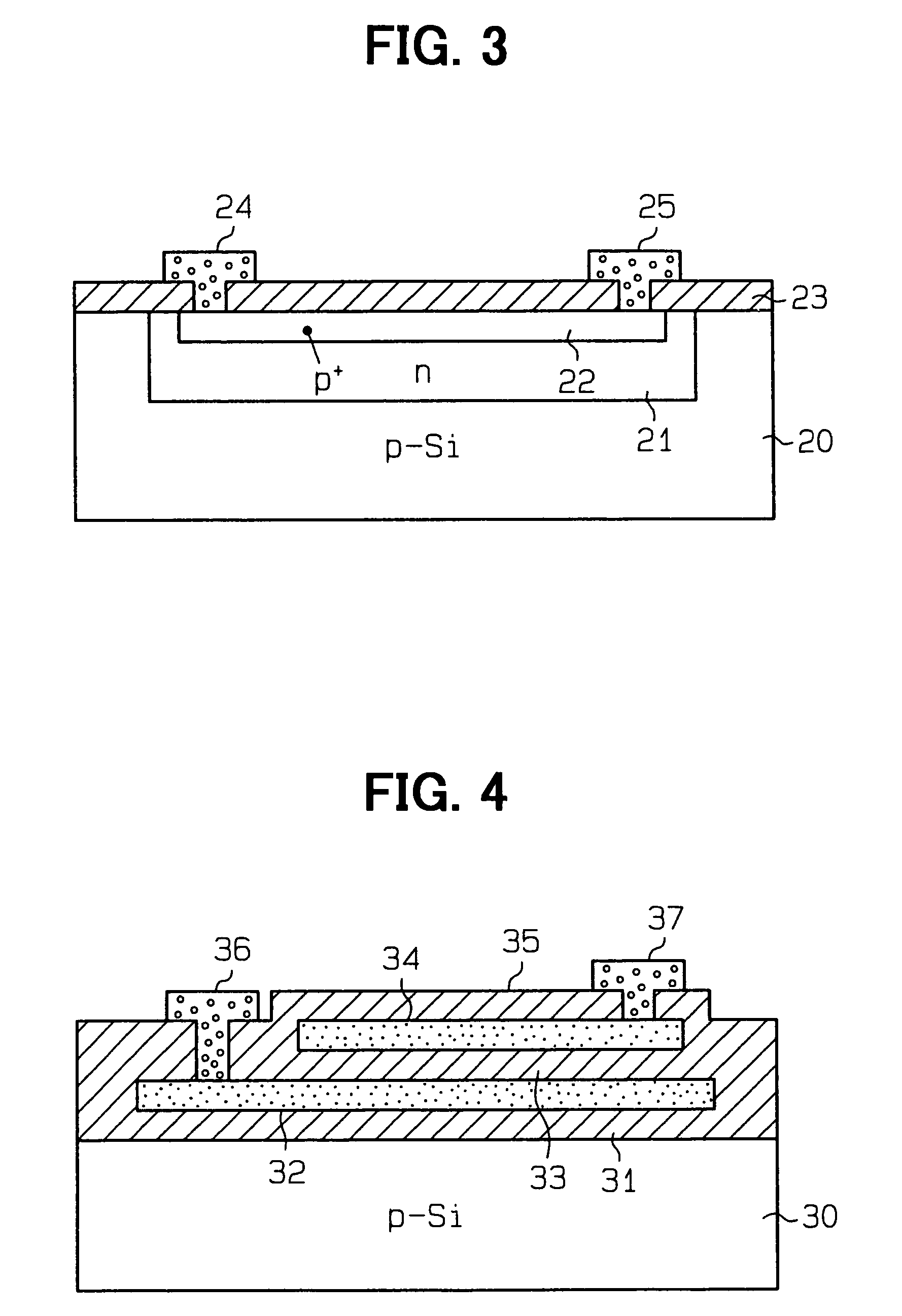
[0040]The resistors 5 and 6 in FIG. 1 may be impurity doped polysilicon resistors as shown in FIG. 2 or diffused resistors as shown in FIG. 3.

[0041]Referring to FIG. 2, a semiconductor element that may implement the resistor 5 (or first resi...

second embodiment

[Second Embodiment]

[0075]Referring to FIG. 15, a second preferred embodiment of the present invention will be described in greater details herein below.

[0076]In FIG. 15 a circuit diagram of an oscillator circuit in accordance with the preferred embodiment is shown. The oscillator circuit in accordance with the preferred embodiment is also preferably built into a chip, i.e., integrated into an IC.

[0077]In FIG. 15, the circuit includes a comparator 80 as an active element. Furthermore, a feedback circuit made of a resistor 81 and a capacitor 82 is used. This feedback circuit (CR circuit) supplies a feedback to one of input terminals (first input terminal) of the comparator 80. Three resistors 83, 84, 85 are connected in series across the power supply terminal (Vdd) and the ground. The node between the resistor 83 and the resistor 84 is connected to the other input terminal (second input terminal) of the comparator 80 through a switch 86. The threshold voltage VtH of the high voltage s...


PUM


Abstract

An oscillator includes first, second and third inverters (1, 2, 3) connected in series. A feedback path is connected from the output terminal of the third inverter (3) to the input terminal of the first inverter 1 through a resistor (5) while a second feedback path is connected from the output terminal of the second inverter (2) to the input terminal of the first inverter (1) through a capacitor (4). The second feedback path further includes a resistor (6) having a temperature coefficient larger than that of resistor (5) is inserted to adjust the charge/discharge trigger voltage and charge/discharge time of the capacitor (4).

Description

CROSS REFERENCE TO RELATED APPLICATIONS[0001]This application is based upon, claims the benefit of priority of, and incorporates by reference the contents of Japanese Patent Application No. 2002-306085 filed Oct. 21, 2002.FIELD OF THE INVENTION[0002]The present invention relates generally to an oscillator circuit and, more particular, to an oscillator circuit composed of semiconductor elements.BACKGROUND OF THE INVENTION[0003]Referring to FIG. 18, an oscillator circuit may include inverters 100, 101, 102 connected in series and in which the output of the inverter 101 and the input of the inverter 100 are connected via a capacitor 103. The output of the inverter 102 and the input of the inverter 100 are connected via a resistor 104. FIG. 19 shows waveforms of the input of the inverter 100 (A), the output of the inverter 100 (B), the output of the inverter 102 (Fout), and the output of the inverter 101 (C) at the room temperature, as the solid line.[0004]The oscillation frequency f1 m...

Claims


Application Information

Patent Timeline
IPC IPC(8): H03B5/20H03K3/354H03K3/011H03K3/0231H03K3/03H03L1/02
CPCH03K3/011H03K3/0231H03K3/0315H03L1/02
Inventor AOYAMA, SEIKIITAKURA, TOSHIKAZU
Owner DENSO CORP
Why Eureka
Try Eureka