RF connectors having ground springs

Active Publication Date: 2006-11-07
PACIFIC AEROSPACE & ELECTRONICS
View PDF24 Cites 69 Cited by
  • Summary
  • Abstract
  • Description
  • Claims
  • Application Information

AI Technical Summary

Benefits of technology

[0019]RF connectors disclosed herein further comprise a highly conductive ground spring member to achieve improved conductance of a ground signal by forming a plurality of first contacts with the ferrule member of the RF connector and a plurality of second contacts with the electronics housing or package. That is, ground springs of the present invention permit the formation of an improved ground connection between the ferrule of the RF connector's hermetic feedthru and the electronics housing or package at points adjacent to the dielectric of the electronics housing or package all the while maintaining the hermeticity of the seal between the RF connector and the electronics housing or package.
[0020]Suitable ground springs according to the present invention exhibit good electrical conductivity and are commonly, but not exclusively, made of stainless steel, including gold- or silver-plated stainless steel, or a copper alloy such as, for example, a beryllium-copper alloy including, but not limited to, an alloy comprising 1% Beryllium and 99% Copper (ASTM B194). Ground springs presented

Problems solved by technology

Such components are subject to faulty operation, degradation, and corrosion resulting from contact with dust, water vapor, gases, and the like, as well as from high temperature and/or pressure conditions.
Because of the differing thermal expansion properties of the electronics housing or 
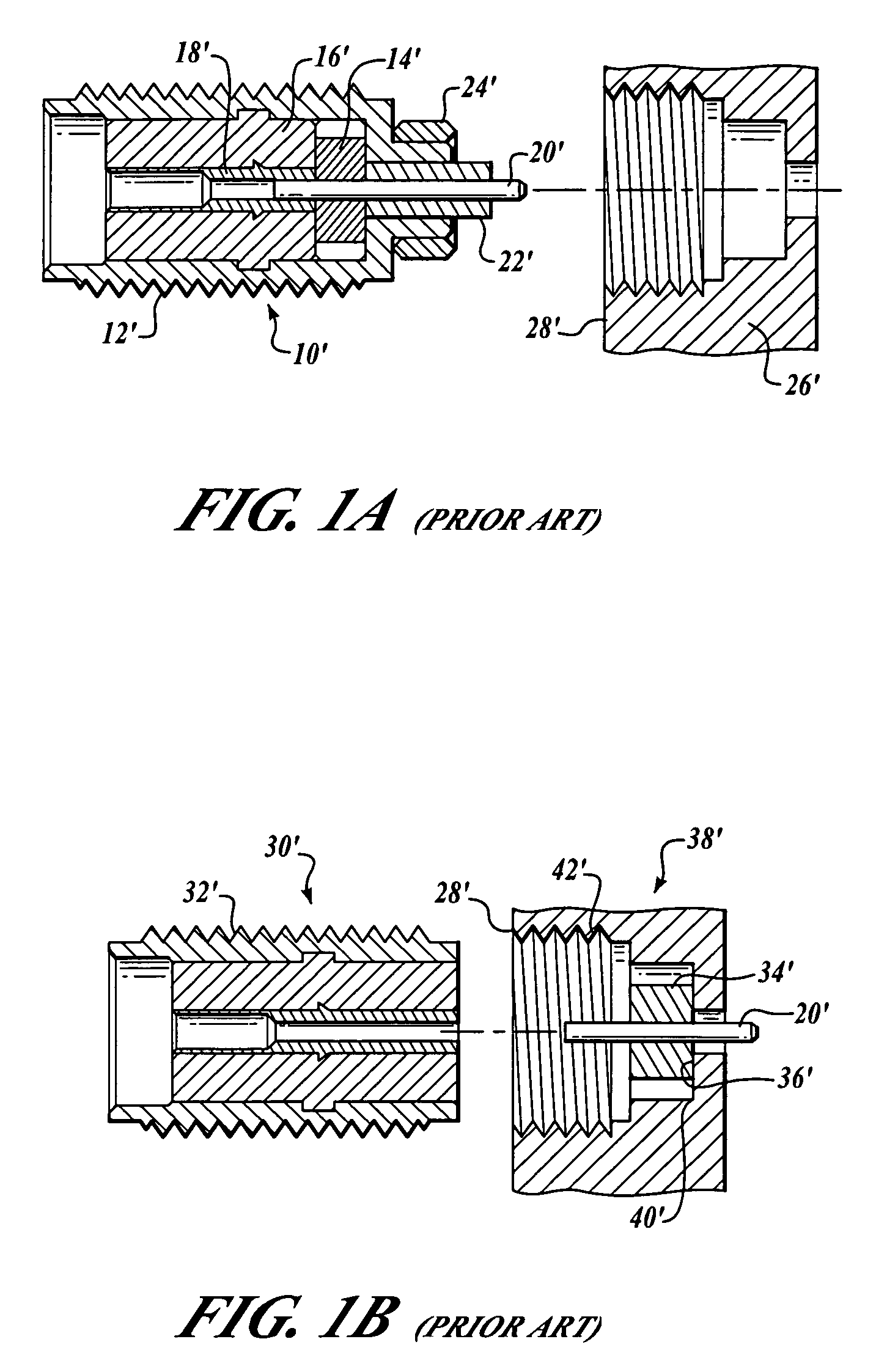
package and prior art “spark plug” type RF connector, i.e. the externally threaded iron-based metal and the internally threaded aluminum metal, the seal between these components does not reliably maintain its hermeticity.
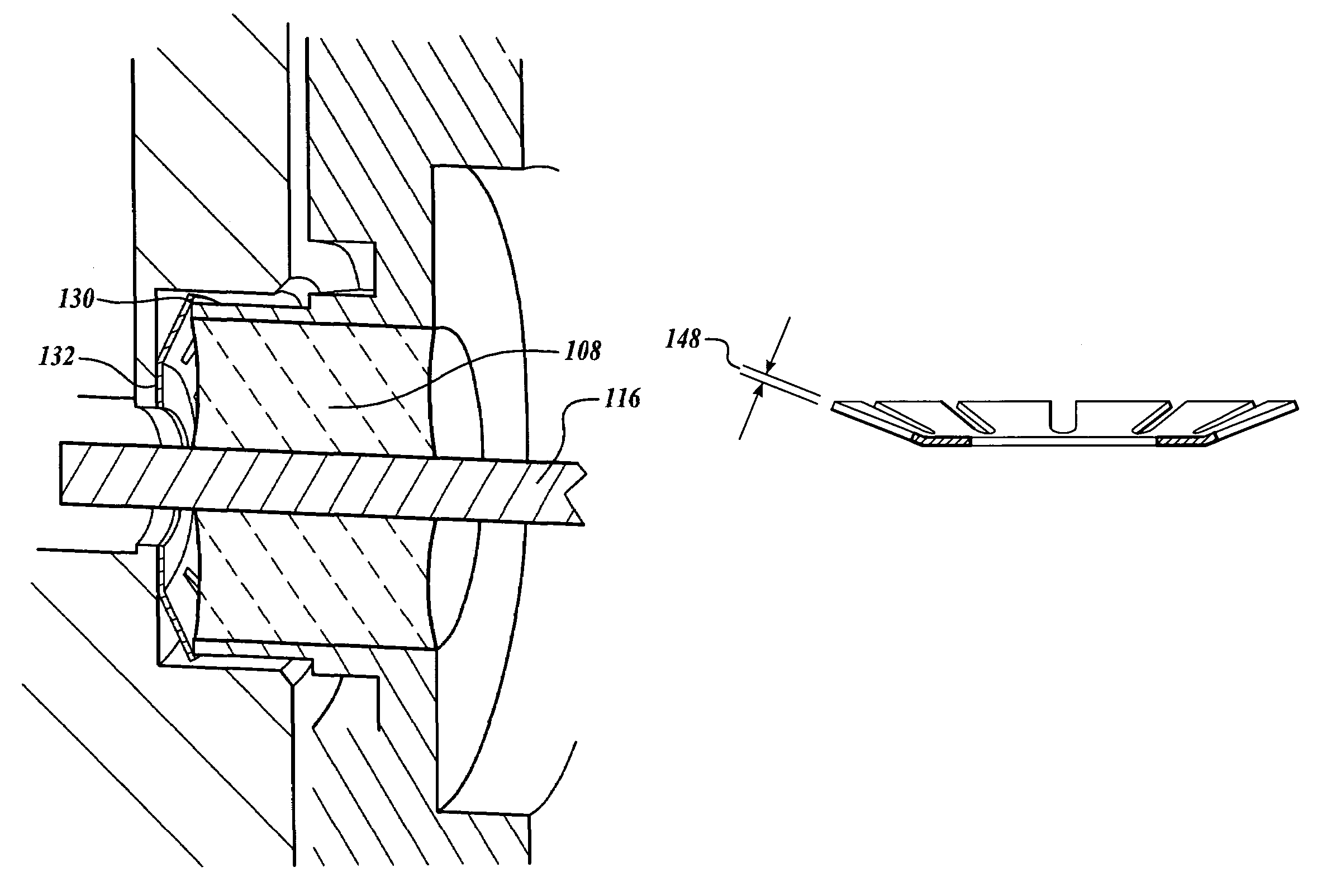
Such phenomena result in fatigue of the solder joint during thermal cycling and cause less than intimate contact between seal ring 24 and electronics housing or package 26 as well as between seal ring 24 and RF connector 10.
Furthermore, the external solder application at 28 prevents RF connector 10 backout by providing a mechanical lock between the components, but because of material fatigue this solder joint also does not form a reliable hermetic seal.
And, this RF connector is not field replaceable because removal of the connector compromises the hermeticity of the package and breaks the rigid connection to the end of the pin located inside the package.
That is, RF connector 10 cannot be replaced in the field without a high risk of compromising the integrity of electronics housing or package 26 circuitry

Method used


Image

  • RF connectors having ground springs
  • RF connectors having ground springs
  • RF connectors having ground springs

Examples


Embodiment Construction

[0034]The present invention is directed to RF connectors that may be employed in conjunction with lightweight, hermetically sealed electronics housing or packages suitable for use in extreme environmental conditions such as those encountered by aircraft and spacecraft. RF connectors presented herein employ one or more ground spring in order to achieve improved conductance of the ground signal from an RF connector to an electronics housing or package. Such inventive RF connectors achieve the practical and reliable installation of hermetic feedthrus into electronics housing or packages by substantially matching the material and / or thermal expansion properties of the electronics housing or package to the corresponding parameters of the inventive RF connector while incorporating one or more ground spring, as disclosed herein, to achieve a more direct ground path.

[0035]As used herein, the term “RF connector” connotes the main body of an RF connector, with a pin insert or other pin interf...


PUM


Abstract

Radio frequency (RF) connectors and electronics housings and packages employing one or more inventive RF connector(s) provided herein utilize a ground spring to achieve improved conductivity of the ground signal by making a plurality of contacts with a ferrule member of the RF connector's hermetic feedthru and a plurality of contacts with the electronics housing or package at points adjacent to an air dielectric. Ground springs used in connection with the present RF connectors maintain predetermined spring properties under compression and/or extreme environmental conditions, including thermal fluctuations, and therefore may be suitably employed in aircraft and spacecraft.

Description

BACKGROUND OF THE INVENTION[0001]1. Technical Field of the Invention[0002]The present invention relates generally to the field of electronics. More specifically, the present invention provides radio frequency (RF) connectors and electronics housings or packages employing one or more inventive RF connector(s). RF connector(s) disclosed herein utilize a ground spring to achieve improved conductivity of the ground signal by making a plurality of contacts with a ferrule member of the RF connector's hermetic feedthru and a plurality of contacts with the electronics housing or package at points adjacent to an air dielectric. Ground springs used in connection with the RF connectors of the present invention maintain predetermined spring properties under compression and / or extreme environmental conditions, including thermal fluctuations, and therefore may be suitably employed in aircraft and spacecraft.[0003]2. Description of the Related Art[0004]Electronic components are used in countless a...

Claims


Application Information

Patent Timeline
IPC IPC(8): H01R9/05
CPCH01R24/42H01R2103/00
Inventor FOSTER, NATHANMEADE, ANTHONY
Owner PACIFIC AEROSPACE & ELECTRONICS
Why Eureka
Try Eureka