

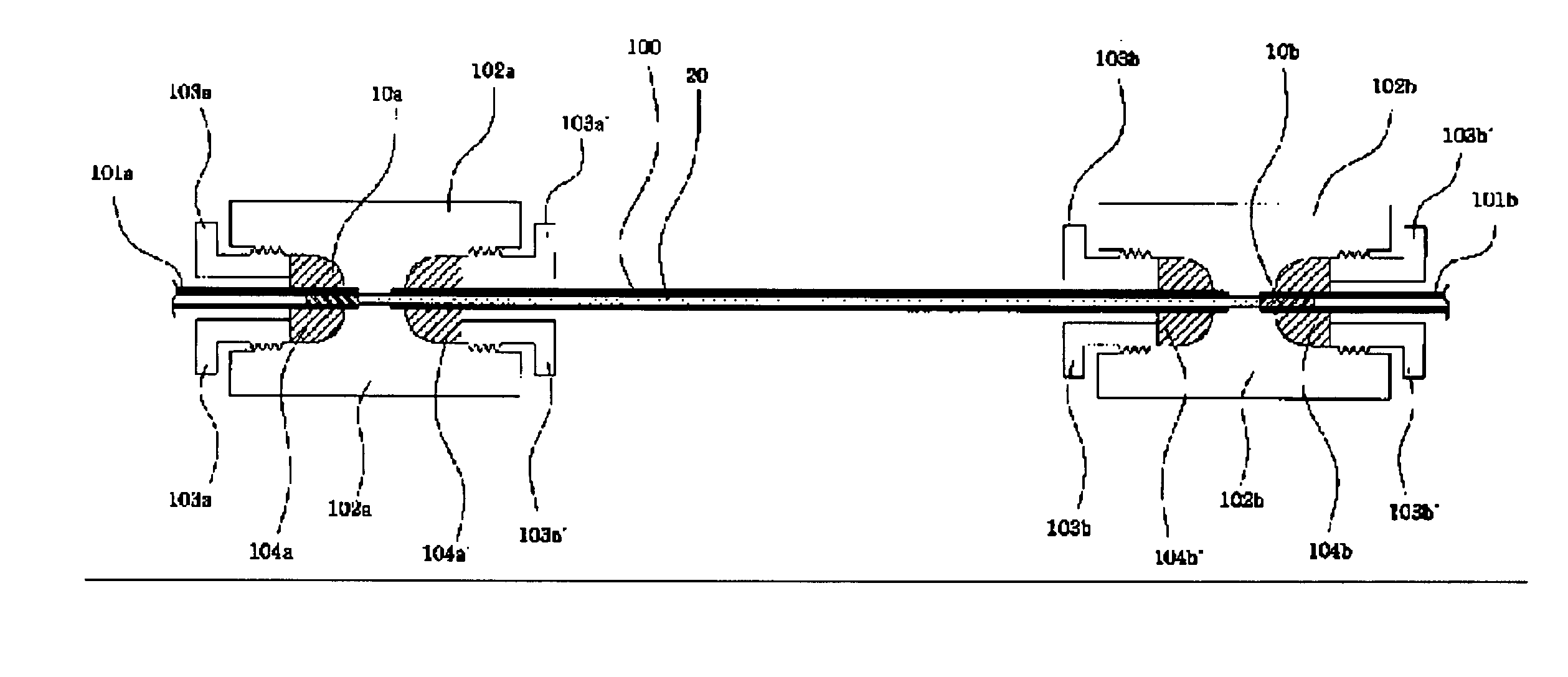
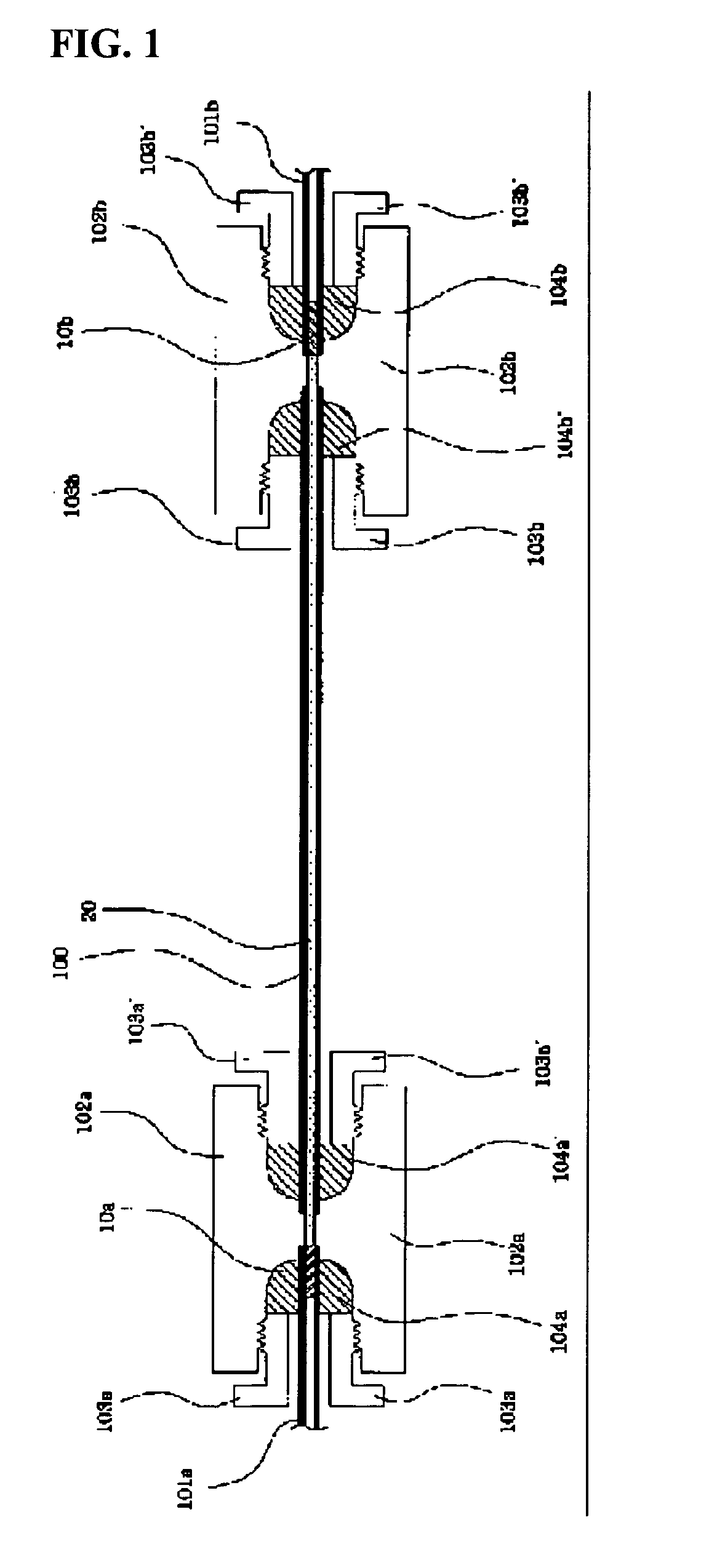
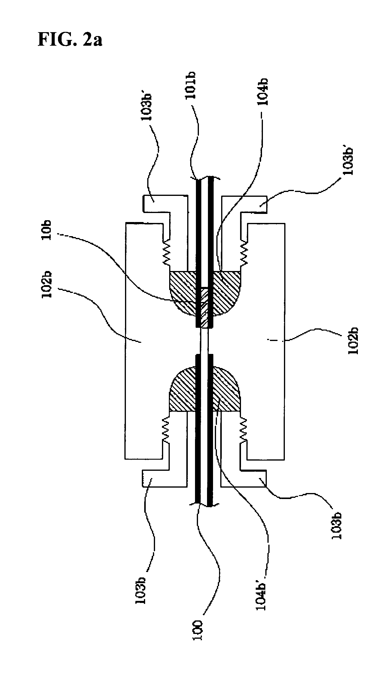
Stainless steel tubing/frit with sintered inorganic particle, the chromatography comprising it, and their manufacturing method
a technology of inorganic particle and steel tubing, which is applied in the direction of filtration separation, separation processes, instruments, etc., can solve the problems of inability to remove fibrils, reduced column efficiency, increased cost and inconvenience of use, etc., and achieves the effect of simple design convenience of column production and low cos
- Summary
- Abstract
- Description
- Claims
- Application Information
AI Technical Summary
Benefits of technology
Problems solved by technology
Method used
Image

Examples
example 1
Production of Metal Tubing / Frit's with Chemically and Thermally Sintered Silica Frits I: 0.1 mm I.D.
[0081]One gram spherical porous 5μ, 60 A° silica particles are dispersed in a 5 mL 10 wt % NaOH solution, and the dispersion is spread over a hard and flat polymer surface as a thin layer, and dried at room temperature under a glass board to protect the dispersion layer from falling dirts. The dried layer is scraped with a polymer scoop and rubbed gently with a round pestle into fine powders. In the microstructure of the above powders observed by a scanning electron microscope (FIG. 4), most of the powders maintain their spherical shapes, and they are partially fused and mixed with minute needle crystals of NaOH. The powders are then uniformly spread on a flat polymer surface with a depth of 2 mm or so. Metal tubings of 5 cm×0.1 mm×1.6 mm (length×I.D. ×O.D.) are located vertically over the fine powders, and are allowed to hit the surface gently and at various spots 50 times to get the...
example 2
Production of Metal Tubing / Frit's with Chemically and Thermally Sintered Silica Frits II: 0.8 mm I.D.
[0085]One gram spherical porous 10μ, 100 A° silica particles are dispersed in a 20 mL 5 wt % KOH solution, and the dispersion is spread over a hard and flat polymer surface as a thin layer, and dried at 50–60° C. under a glass board to protect the dispersion layer from falling dirts. The dried layer is scraped with a polymer scoop and rubbed gently with a round pestle into fine powders.
[0086]The above silica powders are then uniformly spread on a flat polymer surface with a depth of 2 mm or so. Metal tubings of 5 cm×0.8 mm×1.6 mm (length×I.D.×O.D.) are located vertically over the fine powders, and are allowed to hit the surface gently and at various spots 100 times to get the particles in with a depth of 2˜3 mm. The outer wall of the tubing is cleaned with a soft tissue.
[0087]The tubing with the silica powders filled at the tip is placed in an electric furnace and heated at 600° C. f...
example 3
Production of Metal Tubing / Frit's with Chemically and Thermally Sintered Silica Frits III: 0.25 mm I.D.
[0090]One gram spherical porous 5μ, 100 A° silica particles are dispersed in a 10 mL 10 wt % NaOH solution, and the dispersion is spread over a hard and flat polymer surface as a thin layer, and dried at room temperature under a glass board to protect the dispersion layer from falling dirts. The dried layer is scraped with a polymer scoop and rubbed gently with a round pestle into fine powders.
[0091]The above silica powders are then uniformly spread on a flat polymer surface with a depth of 2 mm or so, and metal tubings of 5 cm×0.25 mm×1.6 mm (length×I.D.×O.D.) are located vertically over the fine powders, and are allowed to hit the surface gently and at various spots 100 times to get the particles in with a depth of 2˜3 mm. The outer wall of the tubing is cleaned with a soft tissue.
[0092]The tubing with the silica powders filled at the tip is placed in an electric furnace and heat...
PUM
| Property | Measurement | Unit |
|---|---|---|
| temperature | aaaaa | aaaaa |
| particle sizes | aaaaa | aaaaa |
| diameter | aaaaa | aaaaa |
Abstract
Description
Claims
Application Information